Control unit

a control unit and control panel technology, applied in the direction of emergency protective arrangements for limiting excess voltage/current, electric devices, ac motor stoppers, etc., can solve the problems of large installation space, high cost, and reduced efficiency, and achieve the effect of quick and simple discharge and more rapid recovery

Active Publication Date: 2014-01-16
ROBERT BOSCH GMBH
View PDF7 Cites 9 Cited by
  • Summary
  • Abstract
  • Description
  • Claims
  • Application Information

AI Technical Summary

Benefits of technology

The present invention provides a power inverter with a reduced number of actuations for switching off. It does not require a separate control circuit, saving money and space. The invention allows for a quick and safe shutdown of the inverter, reducing the risk of high induction currents. Overall, the invention improves efficiency and safety.

Problems solved by technology

Such a discharge circuit can be selectively implemented as a permanently energized discharge, which however permanently converts energy from the intermediate circuit capacitor into heat and therefore leads to a reduced degree of efficiency, or even implemented as a discharge circuit which can be switched on or switched off and which must be activated, for example, if an opening of the traction network connector is recognized.
A disadvantage of the known power-off methods is that the individual disconnections are activated using different triggering criteria and therefore require considerable technical complexity, high costs and large installation space.

Method used


Image

  • Control unit
  • Control unit
  • Control unit

Examples


Embodiment Construction

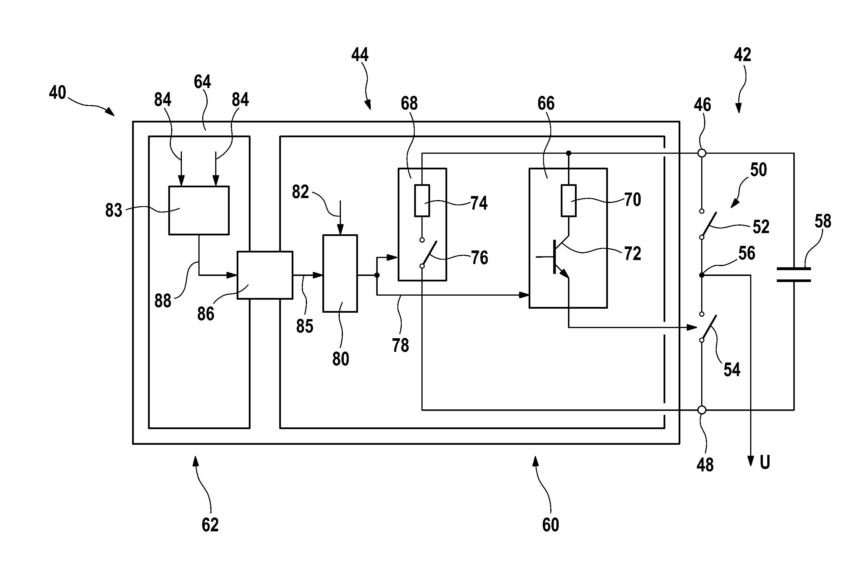
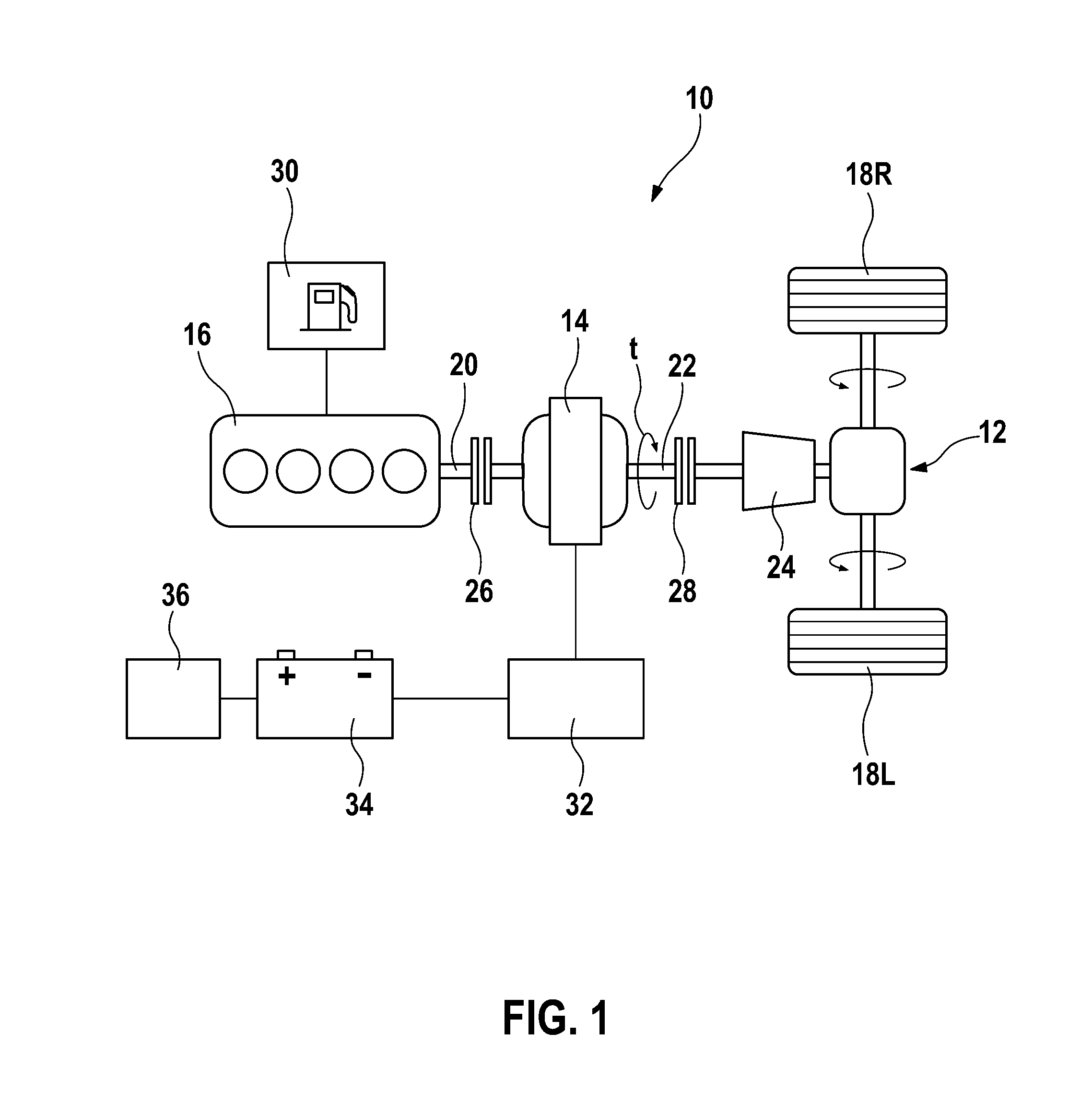
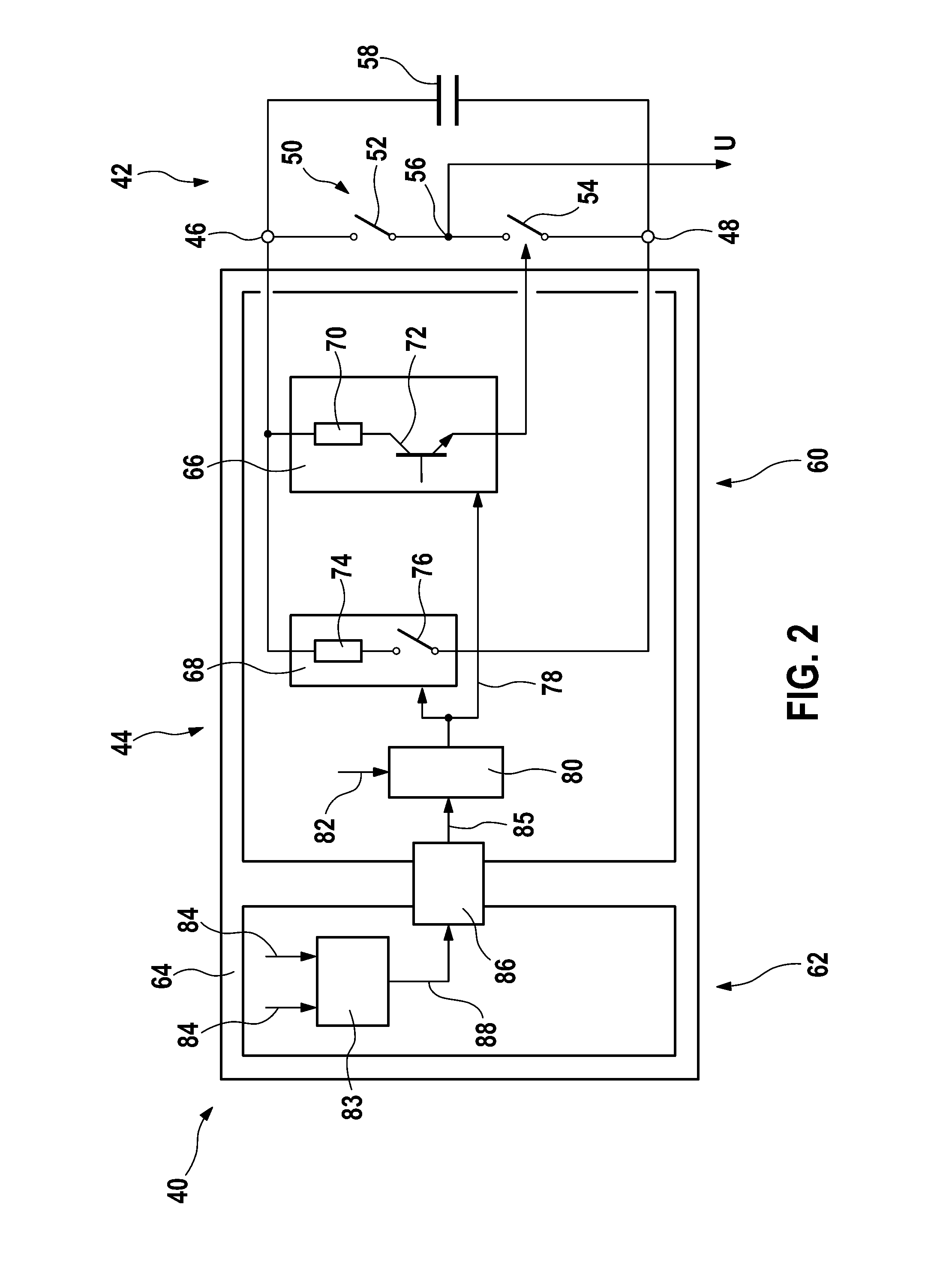
[0033]A motor vehicle is depicted in FIG. 1 and generically denoted with the reference numeral 10. The motor vehicle 10 comprises a drive train 12, which in the present case includes an electric machine 14 and a combustion engine 16 for providing driving power. The drive train 12 serves to drive the wheels 18L, 18R of the vehicle 10.

[0034]The combustion engine 16 is connected or can be connected via a crankshaft 20 to the electric machine 14, wherein said combustion engine 16 and the electric machine 14 provide a torque t at an output shaft 22 which rotates at an adjustable rotational speed. The output shaft 22 is connected or can be connected to a transmission unit 24 in order to transmit the torque t to the wheels 18R, 18L to be driven. The crankshaft 20 and the output shaft 22 each have a clutch 26, 28 in the present case in order to connect the combustion engine 16 to the electric machine 14 or, respectively, the electric machine 14 to the transmission unit 24.

[0035]The drive tr...


PUM


Abstract

The invention relates to a control unit (40) for driving an electric load, in particular an electric machine, having a first and a second voltage terminal (46, 48) in order to supply the control unit (40) with electrical energy, a capacitor (58), which is connected between the voltage terminals (46, 48), at least one half-bridge (15), which is connected between the voltage terminals (46, 48), wherein the half-bridge (50) has two controllable switches (52, 54), between which there is formed a half-bridge tap (50) for connecting the load, a safety circuit (66), which is designed to close one of the controllable switches (52, 54) of the half-bridge (50) in the event of a fault, a discharge circuit (68), which is designed to connect the voltage terminals (46, 48) electrically in the event of a fault, and having a control circuit (18) which is designed to provide a control signal (78) which triggers the safety circuit (66) and the discharge circuit (68) in the event of the detected fault.

Description

BACKGROUND OF THE INVENTION[0001]The present invention relates to a control unit for driving an electric load, in particular an electric machine, having a first and a second voltage terminal in order to supply the control unit with electrical energy, a capacitor, which is connected between the voltage terminals, at least one half-bridge, which is connected between the voltage terminals, wherein the half-bridge has two controllable switches, between which there is formed a half-bridge tap for connecting the load, a safety circuit, which is designed to close one of the controllable switches of the half-bridge in the event of a fault, and a discharge circuit, which is designed to connect the voltage terminals electrically in the event of a fault.[0002]The present invention further relates to a method for initiating a safety mode of a control unit for driving an electric load, in particular an electric machine, wherein the control unit has a first and a second voltage terminal in order ...

Claims


Application Information

Patent Timeline
IPC IPC(8): H02H9/00B60L50/16
CPCH02H9/00B60L3/04B60L7/06H02P3/22B60L3/003B60L2210/40B60L50/16Y02T10/64Y02T10/72Y02T10/7072Y02T10/70
Inventor SCHOENKNECHT, ANDREAS
Owner ROBERT BOSCH GMBH
Why Eureka
Try Eureka