Hub pulling device and method for use

a technology of a hub and a pull rod, which is applied in the direction of metal-working equipment, metal-working equipment, manufacturing tools, etc., can solve the problems of difficult maintenance, especially the drive components, and difficult separation, and achieve the effect of quick and easy removal of the hub

Active Publication Date: 2014-01-16
TITERA JERRY
View PDF1 Cites 1 Cited by
  • Summary
  • Abstract
  • Description
  • Claims
  • Application Information

AI Technical Summary

Benefits of technology

The patent text describes a hub pulling device for skid-steers that is designed to easily remove the hub from its axel. The device includes a circular plate with holes to receive the bolts of the hub, a center bore, and gussets that support the plate. A pin is inserted into the center bore for easy removal of the hub. The plate is made of strong and durable ¼ inch steel, while the pin is made of a single piece of material for durability and precision. The technical effect of this device is to simplify the process of changing hubs on skid-steers, making it faster and easier for operators to maintain vehicles.

Problems solved by technology

Although the skid-steer is an extremely capable device, it is the conditions the skidsteer operates within that make maintenance difficult, especially the drive components.
The operation of the skid-steer within cold, wet, muddy, and dirty environments tends to seal parts together making separation difficult.

Method used


Image

  • Hub pulling device and method for use
  • Hub pulling device and method for use
  • Hub pulling device and method for use

Examples


Embodiment Construction

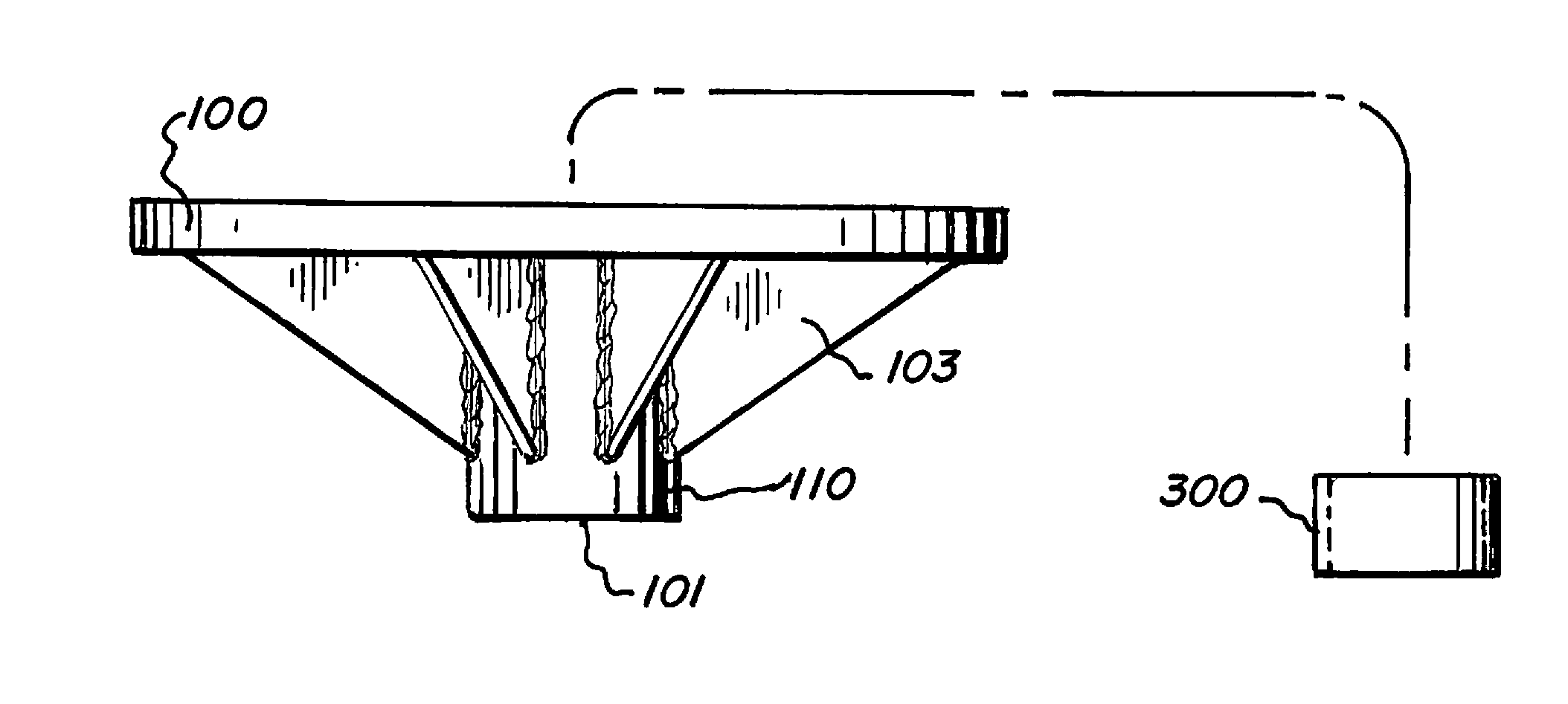
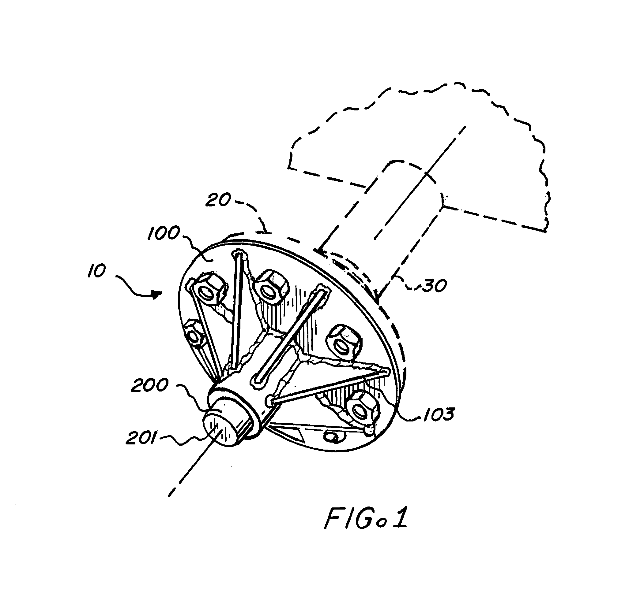
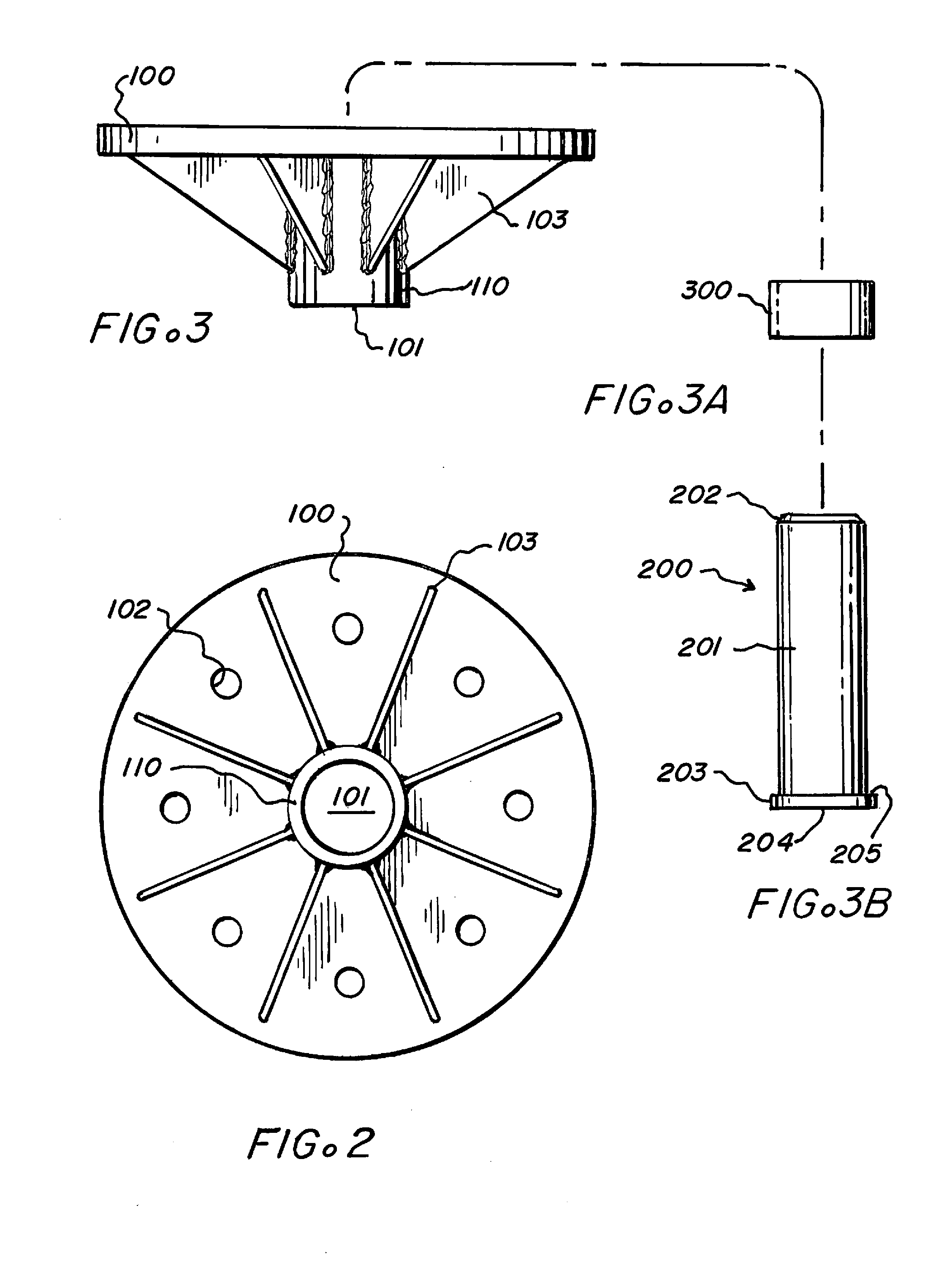
[0021]Referring now to FIG. 1-FIG. 3B there is shown an embodiment of the hub pulling device of the present invention, generally designated by the reference numeral 10 designed to quickly and easily removes the hub 20 from an axel 30 of a vehicle. More particularly, this device 10 is configured to remove the hub 20 from the axel 30 of a skid-steer. The device 10 includes a circular plate 100 forming a flange with a plurality of through holes 102 aligned to receive the lug bolts of the hub 20, a center bore 101 centrally located within the plate 100, the center bore 101 having a circular sidewall 110 defining a circumference of the central bore 101, a plurality of gussets 103 in communication with the plate 100 and supporting the sidewall 110, and a pin 200 removably received within the central bore 101.

[0022]The pin 200 has a head 203 and a shaft 201. The shaft 201 is attached to the head 203 and extends to a first end 202 opposite the head 203. The shaft 201 has a diameter less tha...


PUM

PropertyMeasurementUnit
diameteraaaaaaaaaa
heightaaaaaaaaaa
circumferenceaaaaaaaaaa

Abstract

A hub pulling device for the removal of a hub from the axel of a vehicle. The device includes a pin and plate. The plate having a central bore having a sidewall supported by a plurality of gussets. The plate containing a plurality of apertures aligned to be received on the lug bolts of the hub. The pin having a head sized for receipt within the hub center and engagement of the axel and a shaft sized for receipt within the central bore. To remove a hub, the pin is placed within the central bore and the plate is mounted to the lug bolts using the lug nuts, the opposed force of the pin pushing on the axel and the plate pulling the hub frees the hub.

Description

CROSS REFERENCE TO RELATED APPLICATIONS [0001]Not ApplicableFEDERALLY SPONSORED RESEARCH [0002]Not ApplicableSEQUENCE LISTING OR PROGRAM [0003]Not ApplicableFIELD OF THE INVENTION[0004]The present invention relates to a device that allows a user to easily remove a hub from the axel of a vehicle. More specifically the device is configured to remove the hub from the axel of a Bobcat® brand skid-steer loader.BACKGROUND OF THE INVENTION[0005]A standard skid-steer loader or skid loader, as they are sometimes called, is a small, but versatile, utility vehicle containing a rigid frame, a pair of lift arms, and four wheels. The wheels of the skid-steer operate in a synchronized fashion on each side, such that device can maneuver quickly and easily by turning one side of wheels faster than the opposed side. This configuration allows the skid-steer to complete tasks in several construction, farm, and utility environments in all seasons and weather with ease.[0006]Although the skid-steer is an...

Claims


Application Information

Patent Timeline
Patent Type & Authority Applications(United States)
IPC IPC(8): B23P19/04
CPCB25B27/023Y10T29/53861Y10T29/49815Y10T29/538
Inventor TITERA, JERRY
Owner TITERA JERRY
Why Eureka
Try Eureka