
Camera System and Method for Observing Objects at Great Distances, in Particular for Monitoring Target Objects at Night, in Mist, Dust or Rain

a camera system and object technology, applied in the field of cameras and methods for observing objects at a large distance, can solve the problems of inability to monitor objects 24 hours a day, inability to use real-time surveillance, and insufficient natural illumination of known cameras, and achieve the effect of greater color contrast and high nir sensitivity

Inactive Publication Date: 2014-01-09
EADS DEUT GMBH
View PDF11 Cites 14 Cited by
  • Summary
  • Abstract
  • Description
  • Claims
  • Application Information

AI Technical Summary

Benefits of technology

The present invention aims to improve observation quality by reducing the impact of natural visibility and illumination conditions. It proposes an IR illumination system that can provide a high-quality observation even in poor visibility and weather conditions. The duration of the IR pulse should not be too short, as it should be greater than a certain percentage of the time required for the transit of the distance from the camera system to the object being observed. This controls the radiation energy within each IR pulse and minimizes "dead times" in the system operation.

Problems solved by technology

These known cameras, however, can only be used with sufficient natural illumination and sufficiently good visibility conditions, meaning little mist, dust, rain, etc. in the air.
A real-time surveillance, 24 hours around the clock is therefore not possible, and is often prevented by poor visibility conditions.
This method is not suitable for the surveillance of large areas due to the extremely high cost, and due to the dependence thereof on good visibility conditions.
These known methods have the disadvantage that the recognition of targets is very slow, and only proceeds with good visibility and illumination.
Such interfering light sources and / or unintended reflections would blind conventional cameras.
For such a grid-like arrangement of laser diodes and / or optical fibers, by way of example, a very uneven intensity distribution of the emitted IR radiation typically results.
This limitation of the maximum pulse duration makes allowance for the fact that the detection of the “start of the pulse” already reflected by the object by the camera system, given the integration therein of IR illumination means, would typically fail if the “end of the pulse” of the same pulse has not yet left the camera system at this point in time.
In the latter case, the image sensor in practice would already be blinded and / or overloaded by very small undesired reflections and / or backscatter of the IR radiation power inside the camera system, such that a simultaneous imaging of the radiation reflected by the object would be impeded.

Method used


Image

  • Camera System and Method for Observing Objects at Great Distances, in Particular for Monitoring Target Objects at Night, in Mist, Dust or Rain
  • Camera System and Method for Observing Objects at Great Distances, in Particular for Monitoring Target Objects at Night, in Mist, Dust or Rain
  • Camera System and Method for Observing Objects at Great Distances, in Particular for Monitoring Target Objects at Night, in Mist, Dust or Rain

Examples


Embodiment Construction

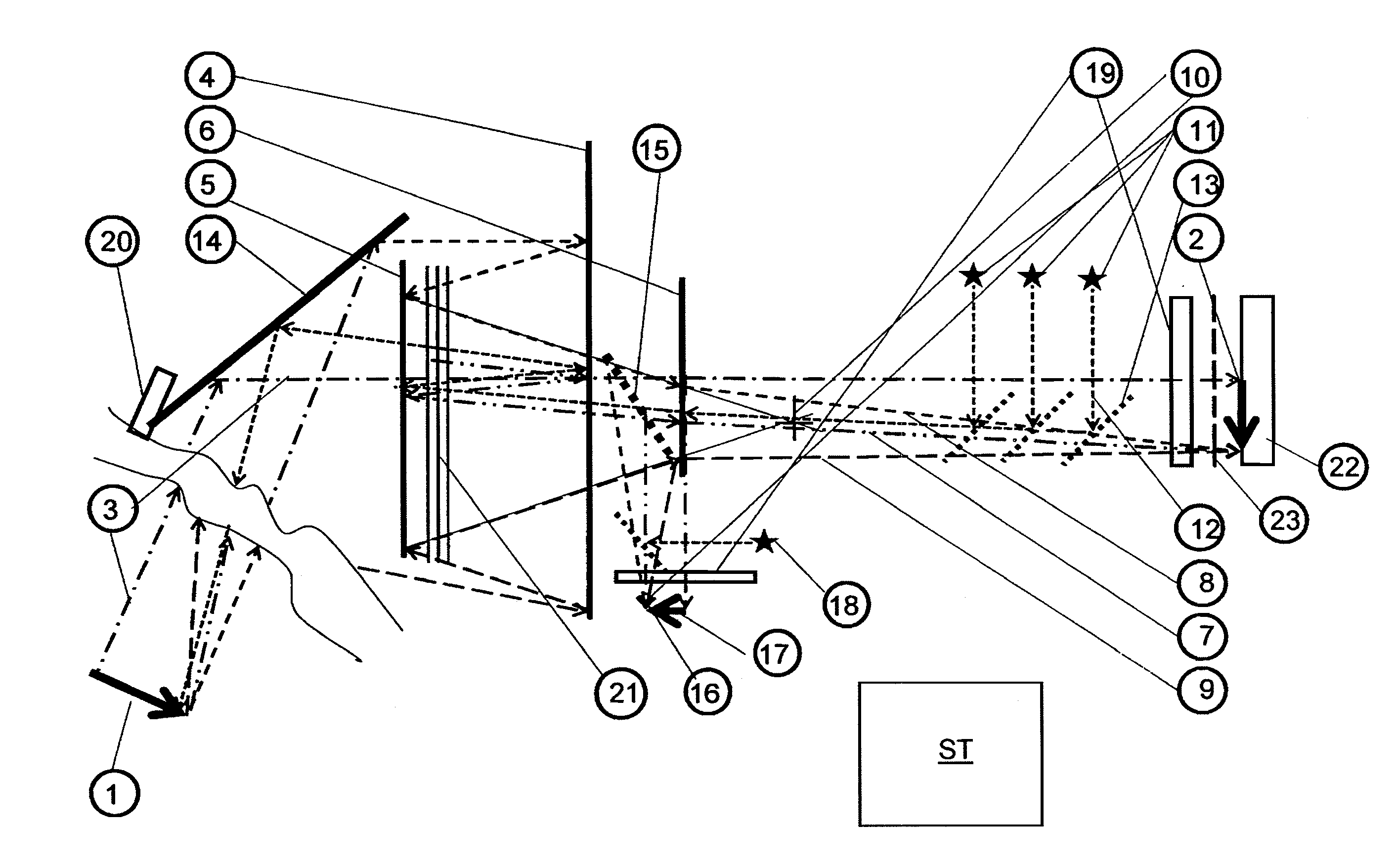
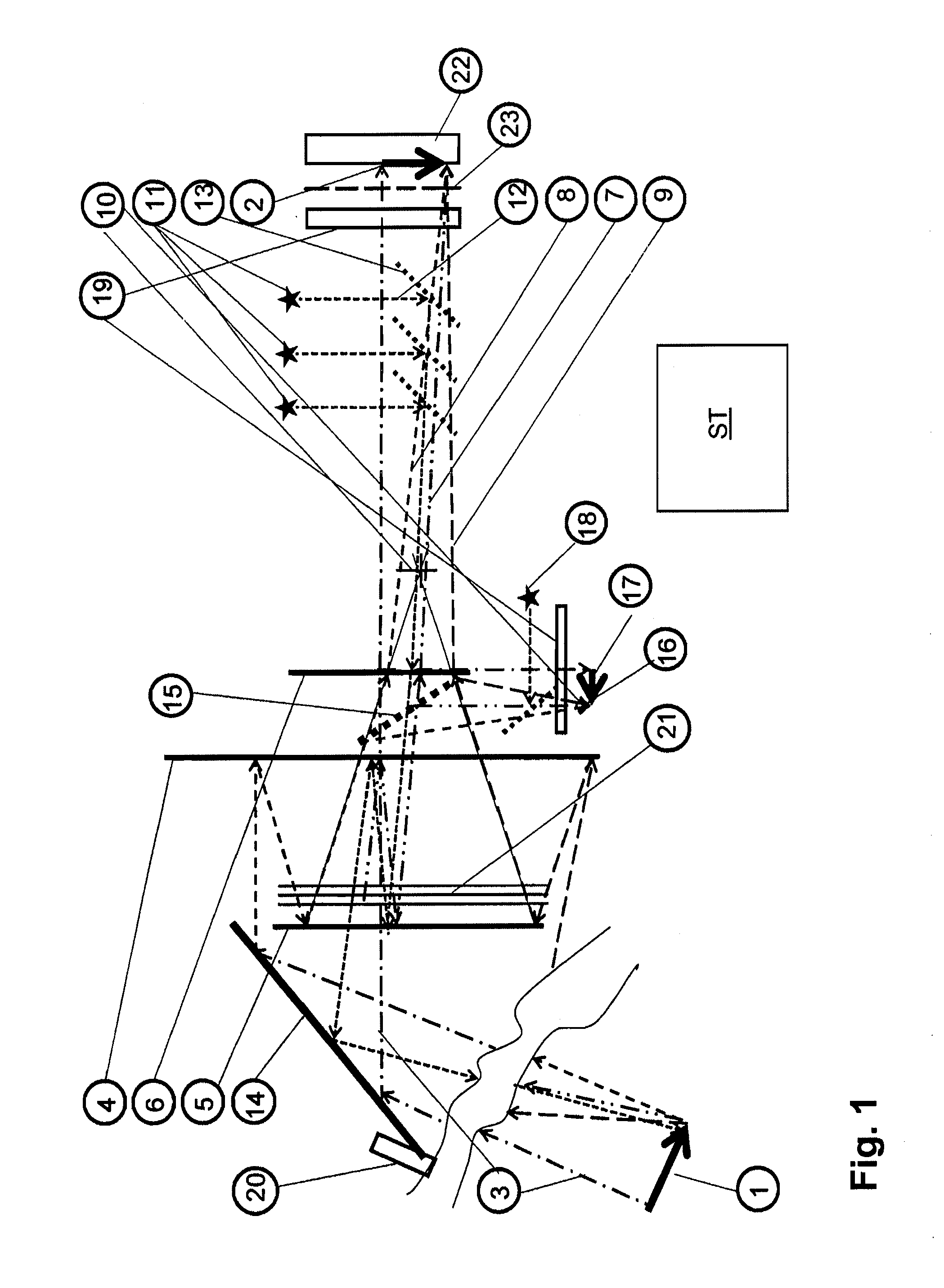
[0067]FIG. 1 shows one embodiment of a multispectral reconnaissance camera, with its own artificial illumination.

[0068]A sufficiently illuminated target object 1 at a large distance (10 to 40 km) is homed on along a line of sight 3 by a telescope 4, 5, and 6, and generates a true image 2 of the target object 1 on the indium gallium arsenide CCD chip of a CCD camera 22 for the near infrared region (sensitive from 0.8 μm to 1.7 μm, with a size of 9.6 mm×7.7 mm, pixel size 30 μm, image size 320 columns by 250 rows).

[0069]The telescope 4, 5, 6 consists of a gold-coated, elliptical primary mirror (“main mirror”) 4 with a diameter of 32 cm (12.5 inches) and a focal distance of 2.54 m, a gold-coated, spherical secondary mirror (“capturing mirror”) 5 in a Cassegraine arrangement, and a special Barlow lens 6, in this case the “fluorite flatfield converter” (from the Baader company), which lengthens the focal distance of the primary mirror 4 adjustably from 4- to 9-times (max 22.86 meters), a...


PUM


Abstract

A camera system and a method for the observation of objects at a large distance at night or through mist, dust, or rain, at an observation distance of 30 to 40 km, includes a pivotable target tracking mirror, a concave primary mirror with a long range, and a convex secondary mirror, which together form a reflecting telescope. The camera system also includes a Barlow lens system, an IR-sensitive image sensor arranged in the image plane of the reflecting telescope, a controllable high-speed shutter system for the image sensor, controllable IR illuminator to illuminate the object being observed by IR illumination pulses of multiple different colors, and a control device that coordinates control of the IR illuminator and of the high-speed shutter system in order to detect multispectral images captured by means of the image sensor according to a gated viewing technique.

Description

BACKGROUND AND SUMMARY OF THE INVENTION[0001]Exemplary embodiments of the present invention relate to a camera system and a method for the observation of objects at a large distance, particularly for the purpose of monitoring target objects at night or in mist, dust, or rain. A “large distance” in this case means any distance greater than 5 km.[0002]In the field of military reconnaissance, by way of example, scenarios are detected by means of multispectral sensors, particularly in a terrain being examined for the presence of facilities, persons, vehicles, infrastructure features, and the like. For this purpose, a large number of images are provided by means of multispectral surveillance cameras, wherein the images must be analyzed under pre-determined time specifications. The objects that must be recognized have any manner of dimensions, and can have a structure characterizing the object and having a complexity varying from low to high. It is possible with known systems to carry out...

Claims


Application Information

Patent Timeline
Patent Type & Authority Applications(United States)
IPC IPC(8): H04N7/18H04N5/33
CPCH04N7/18H04N5/332F41G1/36G02B13/14G02B17/0808G02B17/0852G02B19/0085G02B27/644G03B15/006G03B15/03H04N23/11
Inventor HIEBL, MANFREDPONGRATZ, HANS-WOLFGANG
Owner EADS DEUT GMBH
Learn More