
Scanned Antenna Having Small Volume and High Gain

a scanning antenna and high gain technology, applied in the field of scanning rf antennas, can solve the problems of concomitant increase in the value of the space occupied by each antenna, and achieve the effects of small volume, enhanced gain and scan characteristics, and gain characteristics

Active Publication Date: 2014-01-09
RAYTHEON CO
View PDF5 Cites 3 Cited by
  • Summary
  • Abstract
  • Description
  • Claims
  • Application Information

AI Technical Summary

Benefits of technology

This patent describes a compact antenna that has a small volume compared to conventional antennas. It uses a single radiator and a frequency selective surface to provide enhanced gain and scan characteristics. The antenna has a simple construction, reduced volume, and is a cost-effective solution for various applications. It also has higher reliability compared to other antennas with similar characteristics.

Problems solved by technology

Since there is often a limited amount of space in which to place the antennas, there is a concomittant increase in the value of the space occupied by each antenna.

Method used

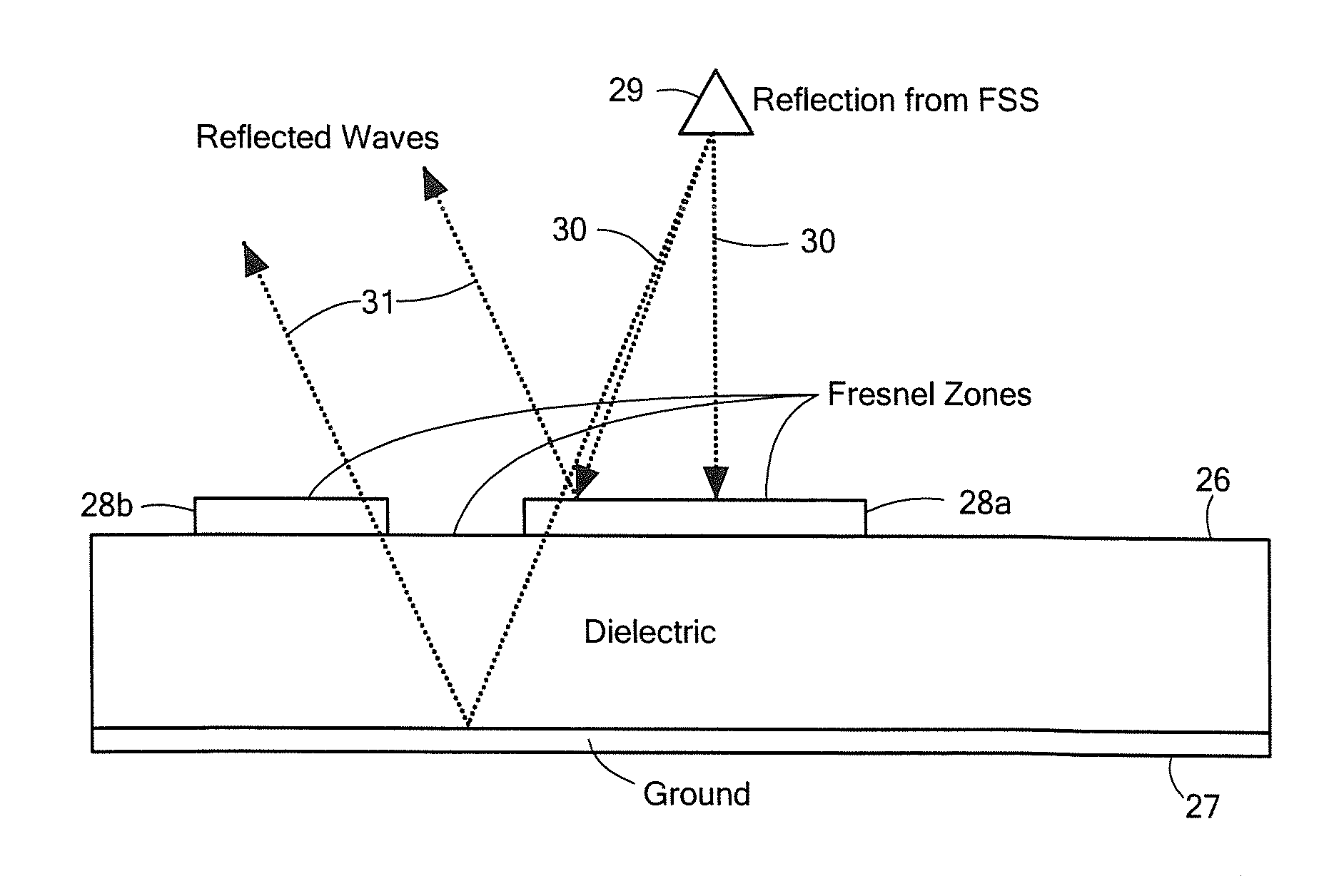

Image

  • Scanned Antenna Having Small Volume and High Gain
  • Scanned Antenna Having Small Volume and High Gain
  • Scanned Antenna Having Small Volume and High Gain

Examples


Embodiment Construction

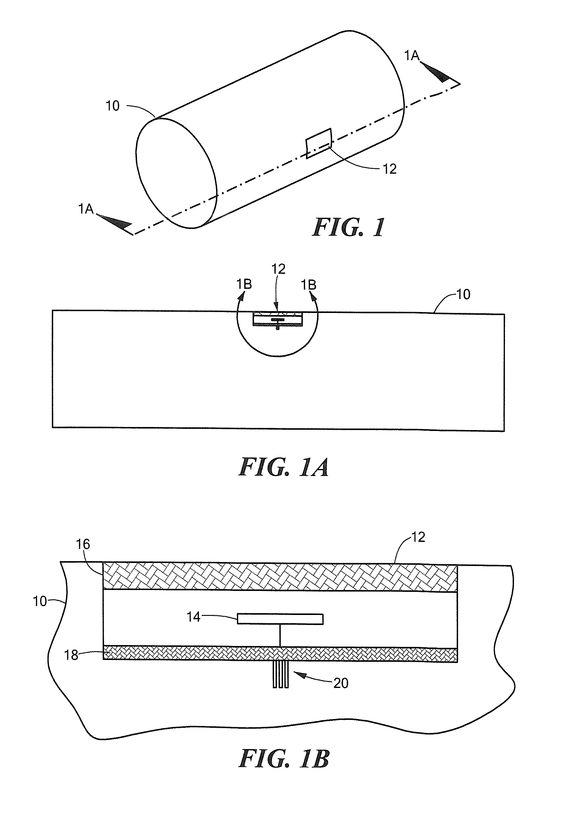
[0017]Referring now to FIGS. 1-1B, in which like elements are provided having like reference numerals throughout the several views, a portion of a structure 10 has disposed thereon an antenna 12. Structure 10 may correspond to a portion of an airborne or land based structure which may be either a stationary structure or a mobile structure. For example structure 10 may be provided as a missile body, an aircraft, a cell tower, or a land based vehicle.

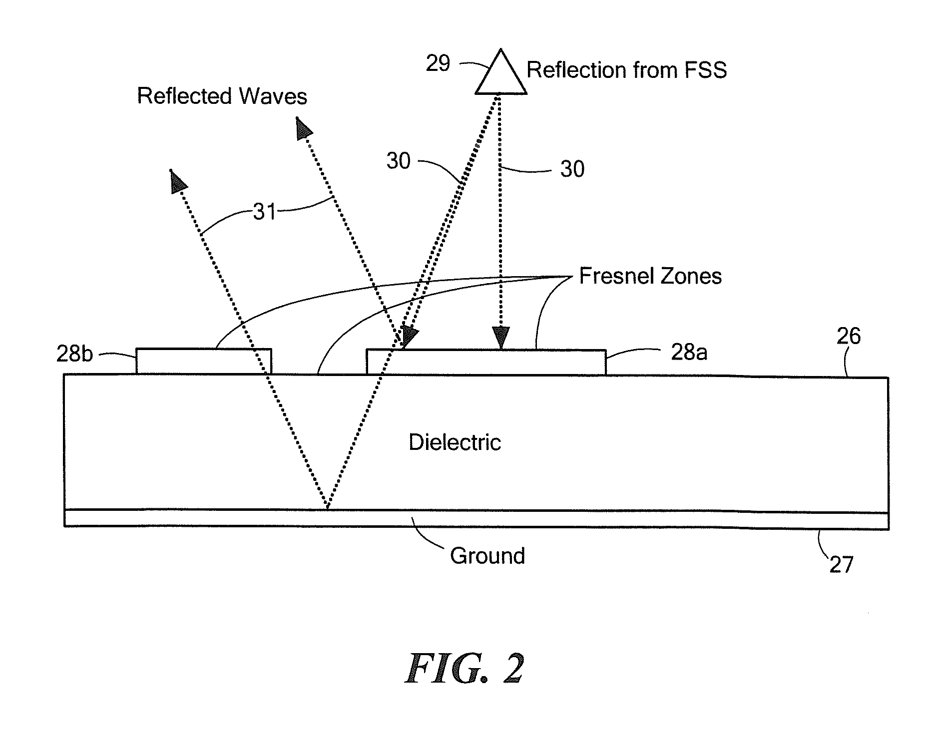
[0018]Antenna 12 includes a single element radiator 14 (FIG. 1B) having first and second opposing surfaces and a frequency selective surface (FSS) 16 disposed above the first surface of the single element radiator 14. In the exemplary embodiment of FIG. 1B, element 14 is provided as a center fed dipole antenna element. A feed 20 couples RF signals to / from antenna element 14. Feed 20 may be provided from a coaxial cable or other type of appropriate feed known to those of ordinary skill in the art. It should be appreciated that other types ...


PUM


Abstract

A scanned radio frequency (RF) antenna having a small volume is described.

Description

FIELD OF THE INVENTION[0001]The system and techniques described herein relate generally to radio frequency (RF) antennas, more particularly, to scanned RF antennas.BACKGROUND OF THE INVENTION[0002]As is known in the art, there is a trend to increase the number of radio frequency (RF) antennas disposed on both commercial and military structures including both airborne and land-based structures and vehicles. Such structures and vehicles may be either stationary or mobile. For example, RF antennas are often disposed on cell towers, missiles, aircraft, and mobile ground based vehicles.[0003]As is also known, there is an increasing trend to place even more RF antennas on such structures. Since there is often a limited amount of space in which to place the antennas, there is a concomittant increase in the value of the space occupied by each antenna. Accordingly, it is desirable to utilize RF antennas which occupy the least amount of space (i.e. occupy the least amount of volume and real e...

Claims


Application Information

Patent Timeline
Patent Type & Authority Applications(United States)
IPC IPC(8): H01Q19/06H01Q1/28
CPCH01Q1/246H01Q1/281H01Q19/065
Inventor ANDERSON, JOSEPH M.LEACH, HERBERT A.GILBERT, CHARLES G.
Owner RAYTHEON CO
Learn More