Frequency mixer

a frequency mixer and mixer technology, applied in the direction of multi-frequency-changing modulation transference, demodulation, electrical equipment, etc., can solve the problems of difficult general type use of high frequency, serious degradation of transmitter characteristics, and difficult to make lo signals, so as to minimize the power of lo leakage

Inactive Publication Date: 2014-01-02
ELECTRONICS & TELECOMM RES INST
View PDF2 Cites 2 Cited by
  • Summary
  • Abstract
  • Description
  • Claims
  • Application Information

AI Technical Summary

Benefits of technology

This patent is about a device called a frequency mixer that is used in high-speed communication systems. The device helps convert signals to different frequencies. The invention helps reduce the unwanted power that can interfere with the signals. The device uses two special mixers that help remove this interference. This makes it easier to transmit information over longer distances with less distortion. The design is simple and can be implemented using a special semiconductor material.

Problems solved by technology

The reason is that, because output signal power of a power amplifier operated in the high frequency is relatively at a low level of power, LO leakage power at a certain level or higher generated from an output of a mixer saturates the power amplifier, such that a characteristic of a transmitter may be seriously degraded.
As described above, a transmitter of a high frequency is difficult to use a general type of a mixer and uses a sub-harmonic type mixer instead.
When a general mixer is used, an LO signal of the E-band demanding power of 10 dBm or higher is required, and it is not easy to make the LO signal.
As mentioned above, because an output level of a power amplifier is relatively low in the transmitter of a high frequency, leakage power of an LO frequency decreased due to the use of the sub-harmonic type mixer may be insufficient.

Method used


Image

  • Frequency mixer
  • Frequency mixer
  • Frequency mixer

Examples


Embodiment Construction

[0016]Hereinafter, exemplary embodiments of the present invention will be described in detail with reference to the accompanying drawings. First of all, we should note that in giving reference numerals to elements of each drawing, like reference numerals refer to like elements even though like elements are shown in different drawings. In describing the present invention, well-known functions or constructions will not be described in detail since they may unnecessarily obscure the understanding of the present invention. It should be understood that although exemplary embodiment of the present invention are described hereafter, the spirit of the present invention is not limited thereto and may be changed and modified in various ways by those skilled in the art.

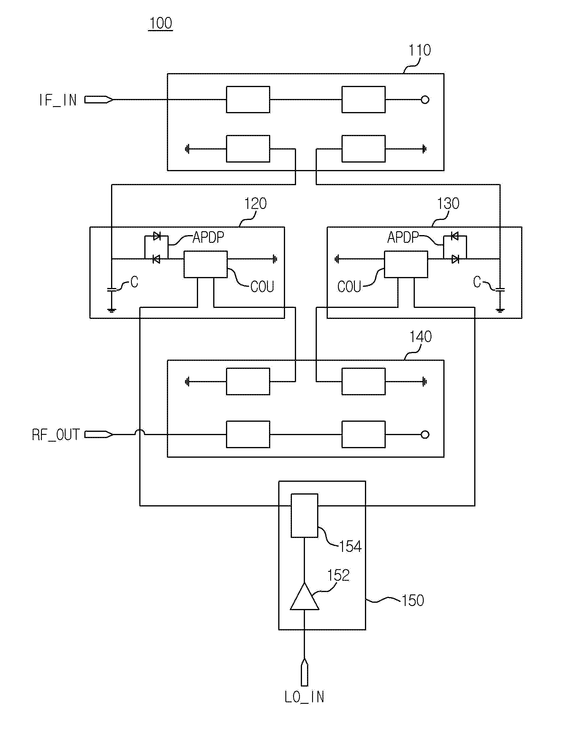
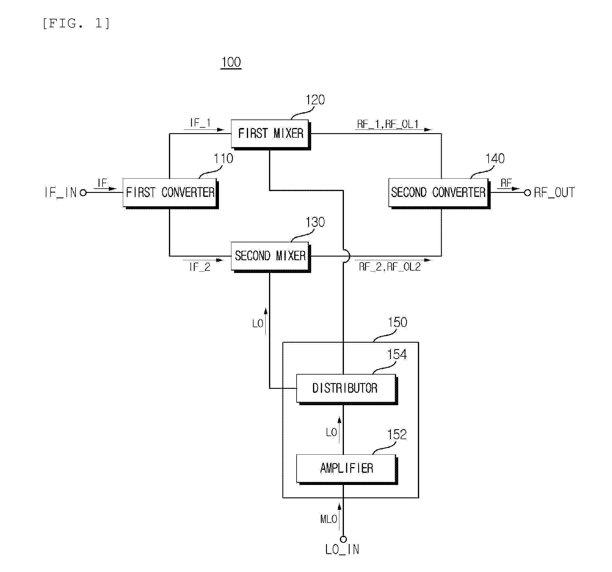
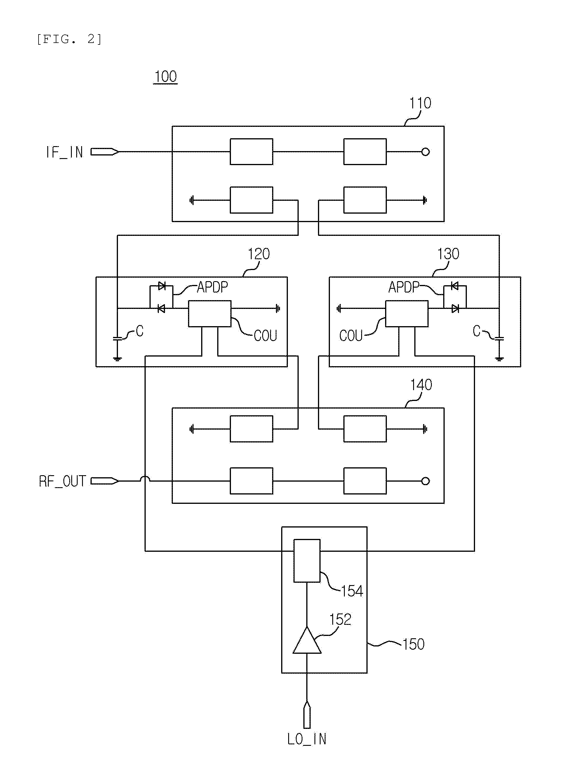
[0017]Hereinafter, a frequency mixer according to an exemplary embodiment will be described in detail based on parts necessary for understanding an operation and an effect with reference to accompanying FIGS. 1 to 3.

[0018]In des...


PUM


Abstract

Provided is a frequency mixer including: an oscillator configured to output an LO signal; a first converter configured to convert an input IF signal into different first and second IF signals; a first mixer configured to output a first RF signal in which the first IF signal is mixed with the LO signal and a first leakage signal; a second mixer configured to output a second RF signal in which the second IF signal is mixed with the LO signal and a second leakage signal; and a second converter configured to mix and attenuate the first and second leakage signals and output an RF signal in which the first and second RF signals are mixed, in order to minimize leakage power of an LO signal generated in a local oscillator in a transmitter for a communication system using a high frequency of 70 GHz or higher, such as an E-band.

Description

CROSS-REFERENCE TO RELATED APPLICATIONS[0001]This application claims priority to and the benefit of Korean Patent Application No. 10-2012-0071849 filed in the Korean Intellectual Property Office on Jul. 2, 2012, the entire contents of which are incorporated herein by reference.TECHNICAL FIELD[0002]The present invention relates to a frequency mixer, and more particularly, to a frequency mixer capable of minimizing leakage power of an LO signal generated in a local oscillator in a transmitter for a communication system using a high frequency of 70 GHz or higher, such as an E-band.BACKGROUND ART[0003]In general, a band of 70 GHz or higher, which is known as an E-band, has attracted much attention worldwide as a next generation point-to-point (P2P) and a wireless backhaul link. E-band communication is known as a band capable of achieving transmission rates of several Gb / s while having a wide bandwidth due to a high carrier frequency. In a communication system using the high frequency, a...

Claims


Application Information

Patent Timeline
IPC IPC(8): H04B1/04
CPCH04B1/0475H03D7/1408H03D2200/009H03D7/02H03D7/16
Inventor JEONG, JIN CHEOLCHANG, DONG PILYOM, IN BOK
Owner ELECTRONICS & TELECOMM RES INST
Why Eureka
Try Eureka