
System for imaging sawn timber

a technology for imaging systems and sawn timber, applied in the field of systems for imaging sawn timber, can solve the problem of consuming longer time for sawn timber to be transported through the apparatus

Inactive Publication Date: 2014-01-02
FIN SCAN
View PDF5 Cites 7 Cited by
  • Summary
  • Abstract
  • Description
  • Claims
  • Application Information

AI Technical Summary

Benefits of technology

The invention allows for several different embodiments, which offer additional advantages. In one embodiment, the measurement area is smaller and easier to implement, making it easier to illuminate. This also means that the measurement conveyor can be shorter.

Problems solved by technology

In the longitudinal method, the transportation of sawn timber through the apparatus takes longer however, as pieces of sawn timber are typically considerably longer than they are wide.

Method used


Image

  • System for imaging sawn timber
  • System for imaging sawn timber
  • System for imaging sawn timber

Examples


second embodiment

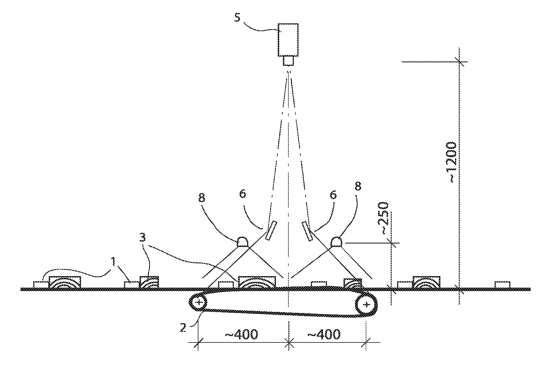
[0016]FIG. 4 shows a schematic drawing of a side view of the arrangement according to a

EMBODIMENTS OF THE INVENTION

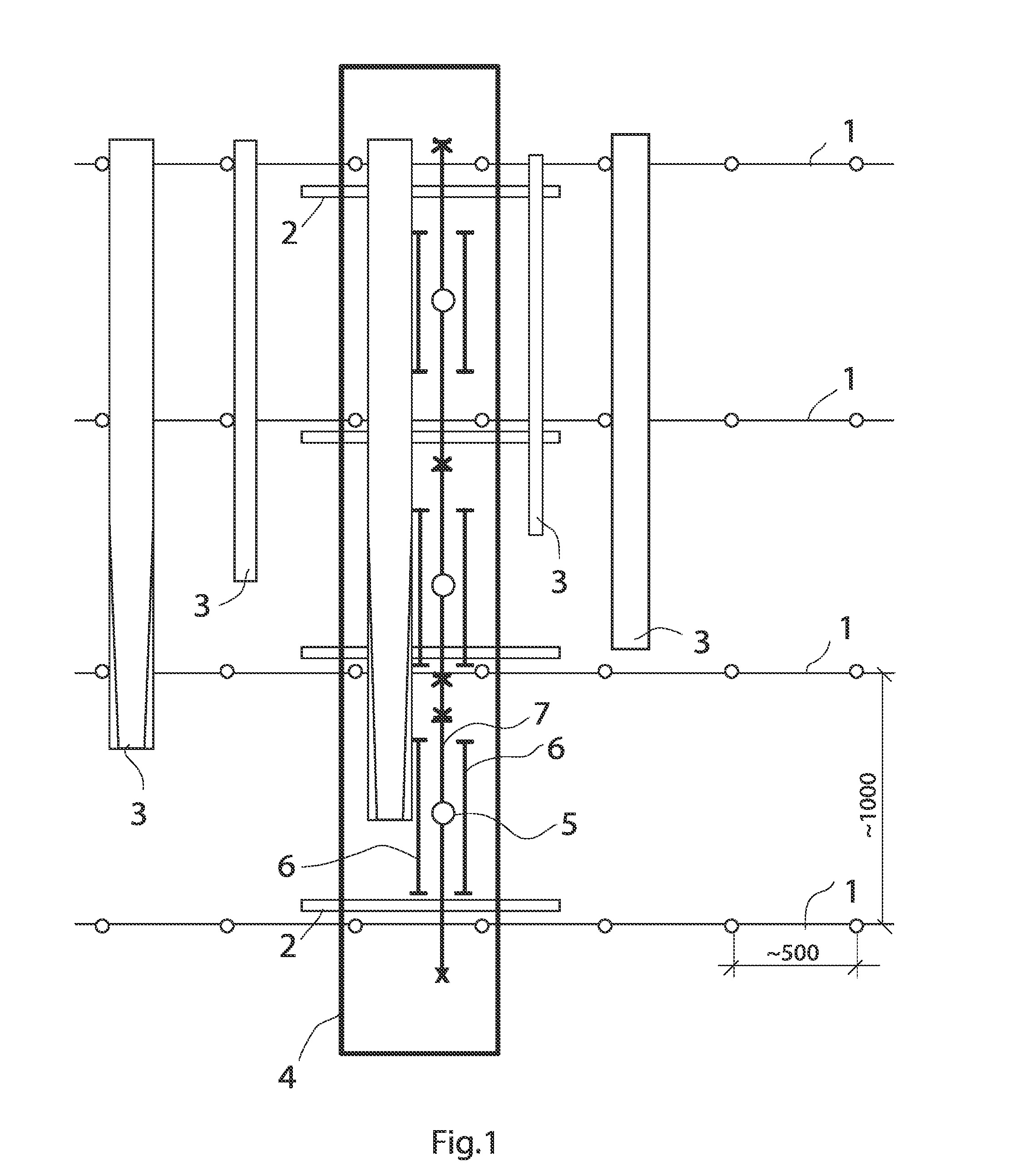
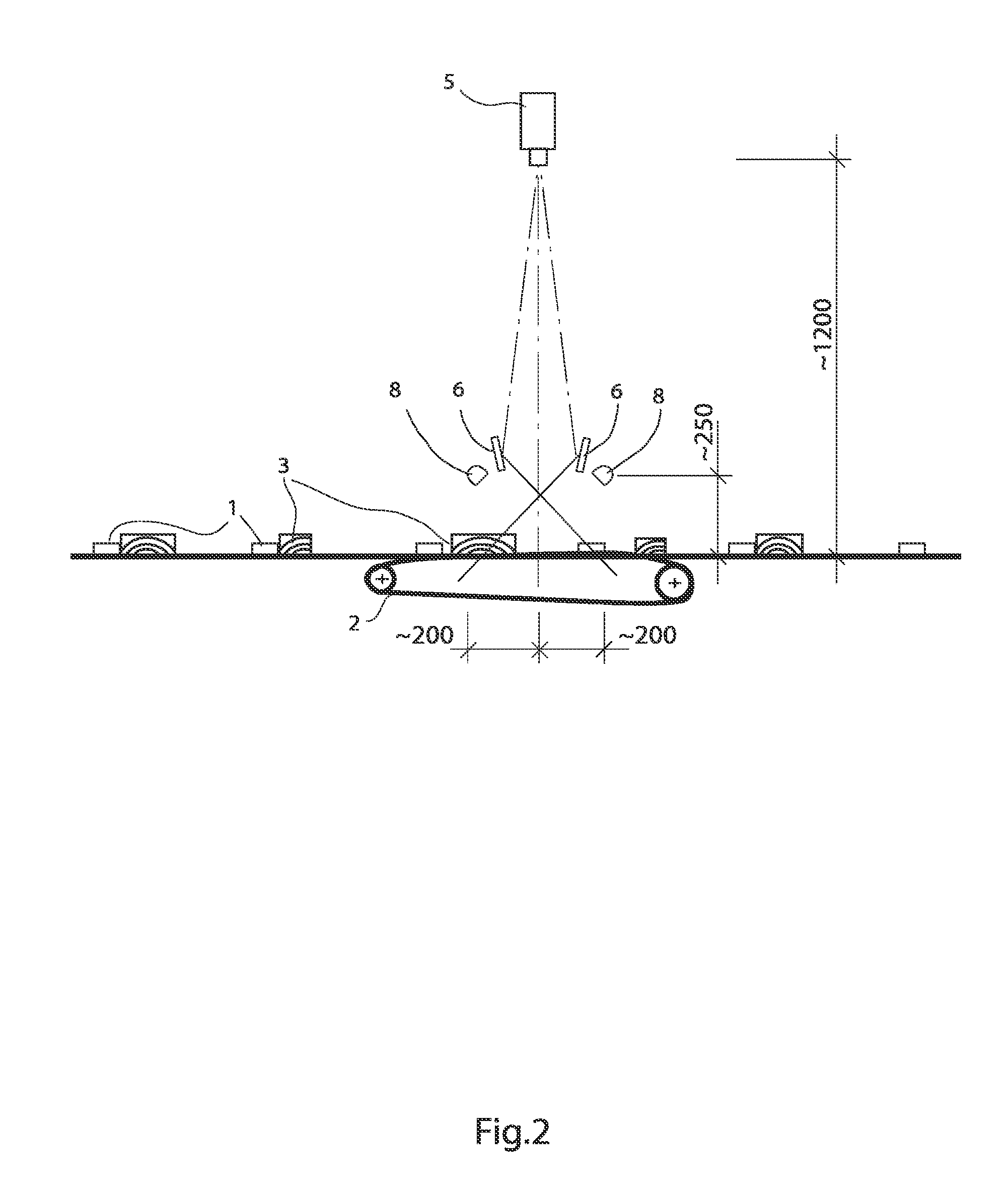
[0017]The system of FIG. 1 comprises a main conveyor 1, which includes a chain and slats for transporting pieces of sawn timber 3 transversely to the measurement conveyor 2 and then away from the measurement conveyor 2. The measurement conveyor 2 is, for its part, typically a belt conveyor.

[0018]The system of FIG. 1 also comprises a measurement station 4, which in turn comprises cameras 5 and mirrors 6, the positioning of which defines the measurement station's 4 measurement area 7, within which measurement area 7 the pieces of sawn timber 3 can be imaged.

[0019]In FIG. 2, the system of FIG. 1 is viewed from the side, i.e. from the direction of the end of a piece of sawn timber 3 in the measuring area 7. The figure shows from the side direction the elements shown in FIG. 1. In addition, the figure shows the lights 8, for illuminating the sawn timber 3, which belong to th...

third embodiment

[0042] the lights 8 are situated in more than two rows of light, which are arranged to illuminate a sawn piece 3 in the measuring area 7 from more than two different directions.

[0043]According to one embodiment, the system comprises a second corresponding group of matrix cameras 5 and mirrors 6 positioned on the path of the sawn pieces 3 between the first group and the sawn-piece rotating device, in such a way that, with the aid of the first group, the top surface and at least one side of each sawn piece 3 can be imaged and, with the aid of the second group, the bottom surface and at least the second side of each sawn piece 3 can be imaged.

[0044]According to an embodiment, the system is adapted to image the pieces of sawn timber 3 during their transverse movement past the measuring area 7 of the system. This means that the operation is continuous. Thus, the main conveyor 1 and / or the measurement conveyor 2 are not stopped for the imaging operation and the pieces of sawn timber are u...


PUM


Abstract

System for imaging pieces of sawn timber travelling transversely past the system. Each piece of sawn timber includes a top surface and a bottom surface, with sides connecting them. The system is arranged to image the top surface and at least one side when the sawn piece travels past the system's measuring area. At least one matrix camera is positioned in a first position relative to the path of the sawn pieces. At least one minor is positioned in a second position relative to the path of the sawn pieces and to the said first position. The first and second positions are selected in such a way that each sawn piece travelling past transversely can be imaged using the at least one matrix camera directly from a first direction and as a mirror image through the at least one mirror from at least one second direction.

Description

[0001]The invention relates to a system for imaging sawn timber.BACKGROUND ART[0002]Publication WO 00 / 62011 A1 discloses an apparatus for determining the dimensions and external properties of timber using the so-called transverse-measurement method.[0003]In the transverse-measurement method, the sawn timber travels past the apparatus transversely, i.e. the apparatus images the pieces of sawn timber essentially simultaneously over their entire length. Correspondingly, the so-called longitudinal method is also known, in which the sawn pieces pass the imaging apparatus in their longitudinal direction, in which case the apparatus images the sawn pieces at one time over their entire width. In the longitudinal method, the transportation of sawn timber through the apparatus takes longer however, as pieces of sawn timber are typically considerably longer than they are wide.[0004]In the apparatus described in publication WO 00 / 62011 A1, the object being measured is examined in transverse mea...

Claims


Application Information

Patent Timeline
Patent Type & Authority Applications(United States)
IPC IPC(8): H04N17/00
CPCH04N17/002G01B11/04G01B11/245G01N21/8986G01N33/46
Inventor KARINEN, SAKARI
Owner FIN SCAN
Learn More