Swash-plate-type compressor

a compressor and plate-type technology, applied in the direction of pump components, positive displacement liquid engines, machines/engines, etc., can solve the problems of reducing suction efficiency and the suction valve may not open at the desired timing, so as to suppress the pulsation and suction efficiency from being lowered, and the size of the compressor is reduced

Inactive Publication Date: 2013-12-26
TOYOTA IND CORP
View PDF9 Cites 0 Cited by
  • Summary
  • Abstract
  • Description
  • Claims
  • Application Information

AI Technical Summary

Benefits of technology

[0029]The present invention provides a swash plate compressor, which is decreased in size while suppresses pulsation and suction efficiency from being lowered.

Problems solved by technology

Thus, the suction valve may not open at the desired timing.
This may decrease the suction efficiency.

Method used


Image

  • Swash-plate-type compressor
  • Swash-plate-type compressor
  • Swash-plate-type compressor

Examples


first embodiment

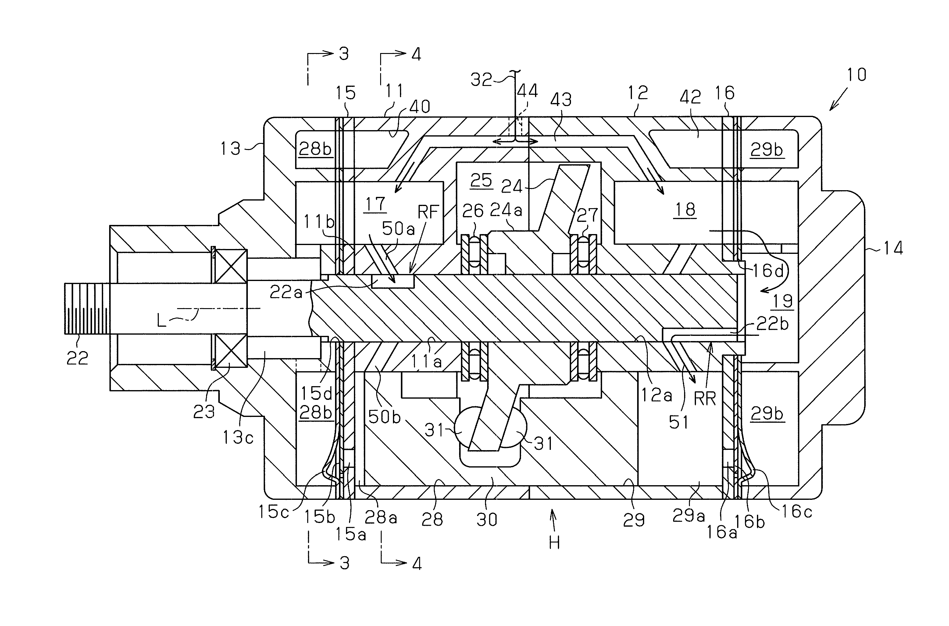
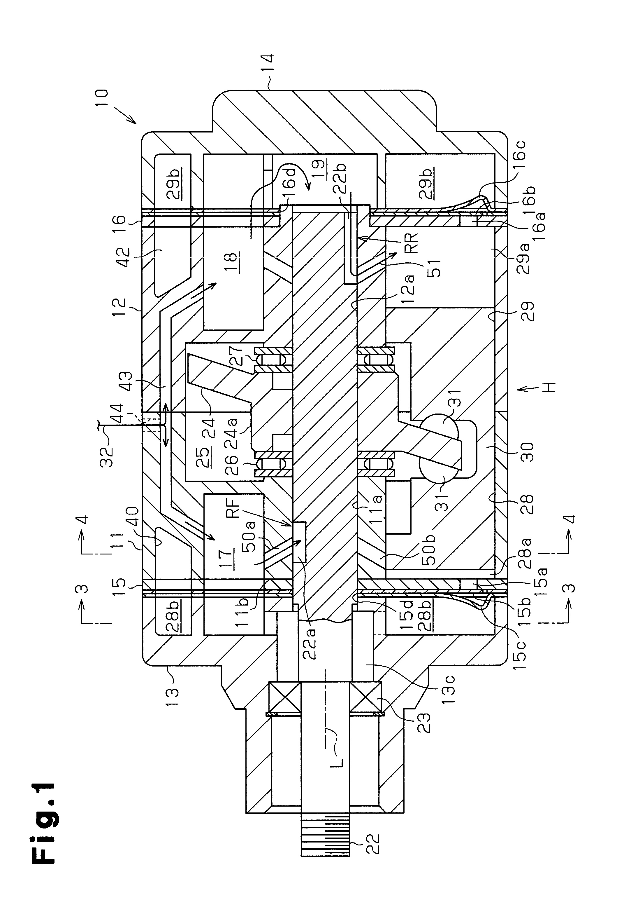
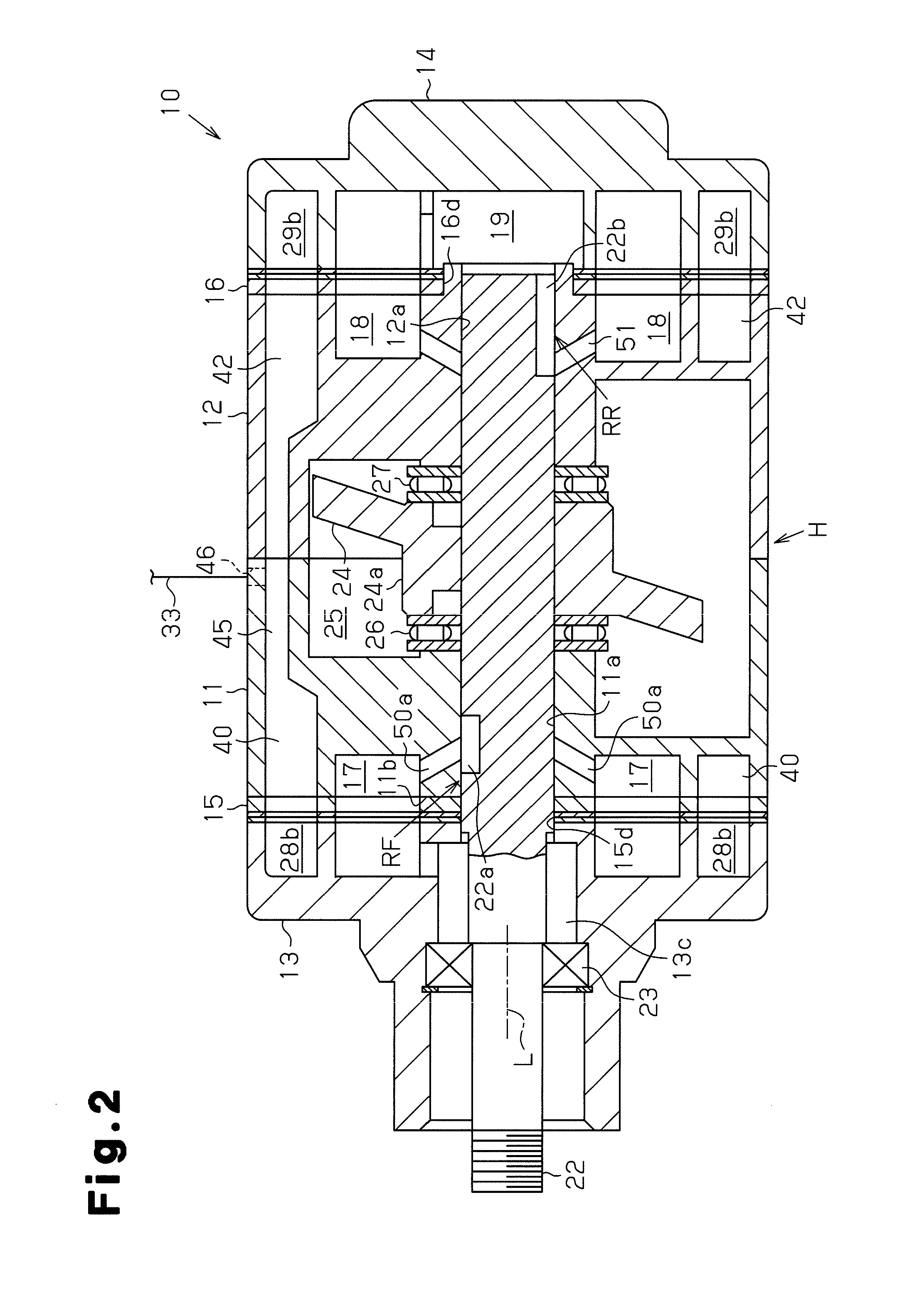
[0044]A first embodiment of the present invention that embodies a swash plate compressor in a double-headed piston type swash plate compressor 10 will now be described with reference to FIGS. 1 to 4.

[0045]As shown in FIGS. 1 and 2, a double-headed piston type swash plate compressor 10 (hereinafter simply referred to as the compressor 10) includes a housing H. A cylinder block 11, which is located at a front side (left side as viewed in FIG. 1), is coupled to a front housing 13 with a front valve / port formation body 15 arranged in between. A cylinder block 12, which is located at a rear side (right side as viewed in FIG. 1), is coupled to a rear housing 14 with a rear valve / port formation body 16 arranged in between. The housing H is formed by the two cylinder blocks 11 and 12 and the front and rear housings 13 and 14 sandwiching the cylinder blocks 11 and 12.

[0046]A rotation shaft 22 is inserted into shaft holes 11a and 12a that are respectively formed in the cylinder blocks 11 and ...

second embodiment

[0092]Next, a second embodiment of the present invention will be described with reference to FIGS. 5 to 7. The same constituents as those in the first embodiment are given the same reference numerals and overlapping description thereof is omitted or simplified.

[0093]As shown in FIGS. 5 and 7(a), a first recess 60 corresponding to each front suction chamber 17 is formed at a portion of a first end face 11b, which is a surface of a cylinder block 11 closer to a front housing 13, located outside of a shaft hole 11a. The first recess 60 is formed in the cylinder block 11 to extend from an inner wall of each front suction chamber 17 in a radial direction. One end of the first recess 60 opens toward the first end face 11b, which is a surface of the cylinder block 11 in an axial direction, and is connected with an open end of each front suction chamber 17. The other end of the first recess 60 is located in the middle of the front suction chamber 17 in the axial direction, and does not exte...


PUM


Abstract

A swash-plate-type compressor of a double-headed-piston configuration, wherein: a front intake chamber is formed set apart from a swash plate chamber so as to be positioned in a narrow space between circumferentially arranged front cylinder bores; and an intake-chamber-communication path is formed in a cylinder block, the intake-chamber-communication path allowing the front intake chamber and a shaft hole to communicate. A front-bore-communication path is formed on the cylinder block, the communication path allowing each of the plurality of front cylinder bores to communicate with the shaft hole. A front rotary valve is provided on a rotating shaft in which a lead-in groove is formed. The lead-in groove allows the intake-chamber communication path and the front-bore communication path to communicate in the stated order, while the lead-in groove rotates integrally with the rotating shaft. In the compact swash-plate-type compressor any decrease in pulsation or intake efficiency is minimized.

Description

TECHNICAL FIELD[0001]The present invention relates to a swash plate compressor including a cylinder block having a shaft hole into which a rotary shaft is inserted, and a plurality of cylinder bores located around the shaft hole and arranged along a peripheral direction. The cylinder bores respectively receive pistons.BACKGROUND ART[0002]For example, Patent Document 1 describes a double-headed piston type swash plate compressor employing a double-headed piston. As shown in FIG. 11, a swash plate compressor 80 of Patent Document 1 includes a cylinder block 81 having three cylinder bores 81a. A double-headed piston 82 is accommodated in each cylinder bore 81a. The cylinder block 81 includes a single suction chamber 83, which is arranged between two adjacent cylinder bores 81a, and a single discharge chamber 84, which is arranged at a different location between two adjacent cylinder bores 81a. The suction chamber 83 and the discharge chamber 84 each having a necessary volume to suppres...

Claims


Application Information

Patent Timeline
Patent Type & Authority Applications(United States)
IPC IPC(8): F04B27/08
CPCF04B27/0839F04B27/1018F04B39/123F04B27/08
Inventor KOBAYASHI, TOSHIYUKIBANNO, NOBUTOSHIISHIKAWA, MITSUYOKONDO, JUN
Owner TOYOTA IND CORP
Why Eureka
Try Eureka