
Bagged Ice Vending Machine

a vending machine and bagged ice technology, applied in the field of vending machines, can solve the problems of inability to adapt, inability to dispense multiple sized pre-packaged ice bags, cost and location, etc., and achieve the effect of convenient and quick dispensing of desired products, low manufacturing cost and easy replenishmen

Inactive Publication Date: 2013-12-26
ABSTON LESTER
View PDF8 Cites 4 Cited by
  • Summary
  • Abstract
  • Description
  • Claims
  • Application Information

AI Technical Summary

Benefits of technology

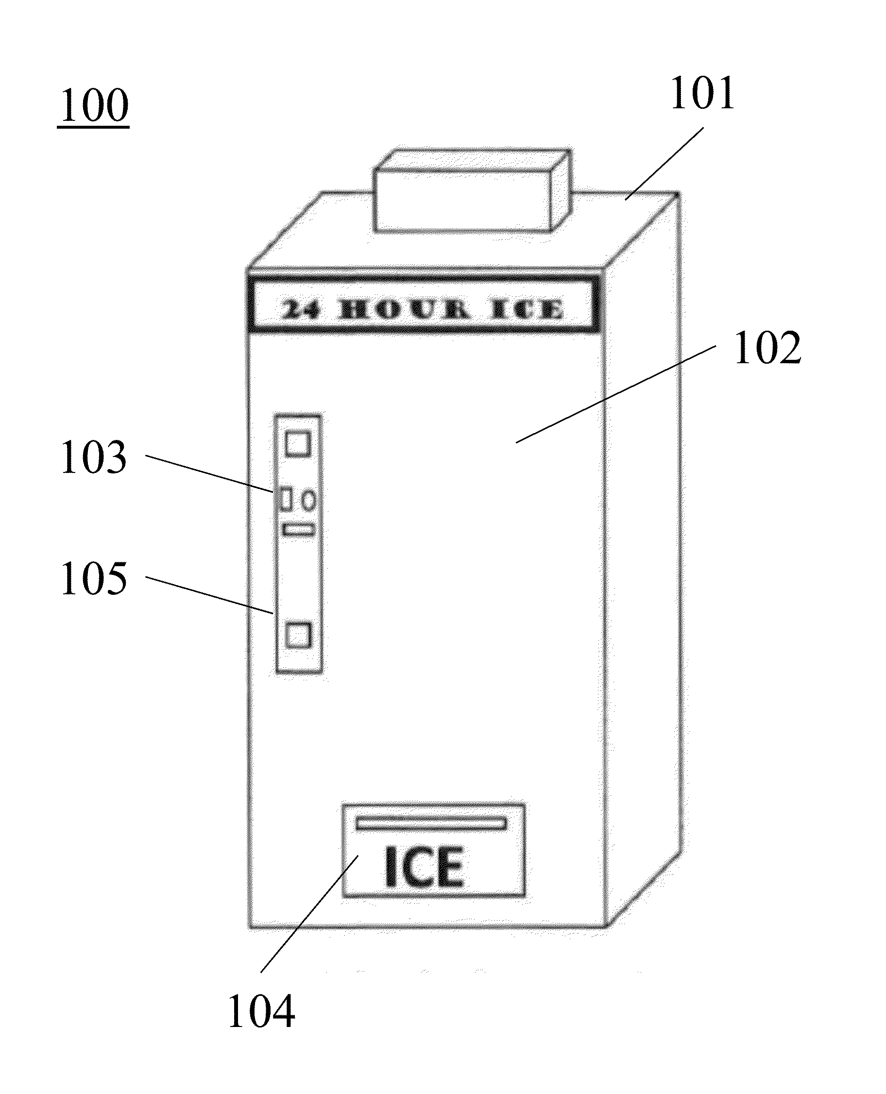
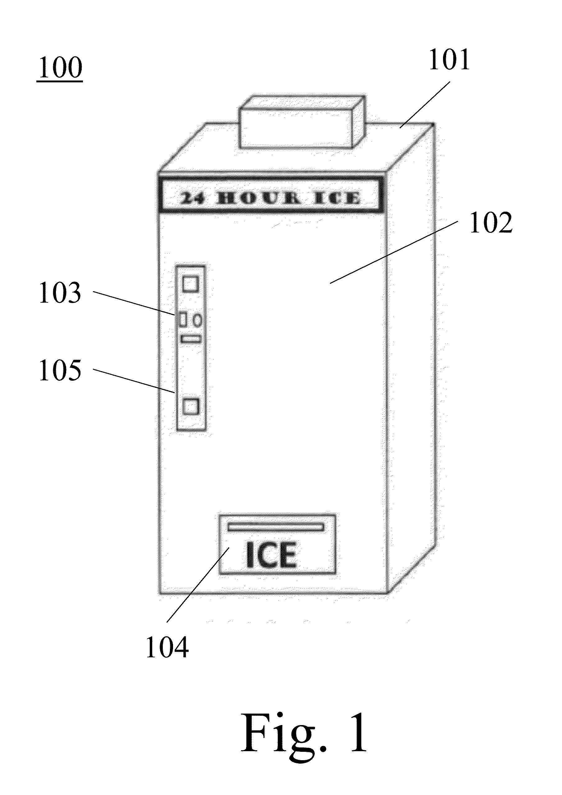
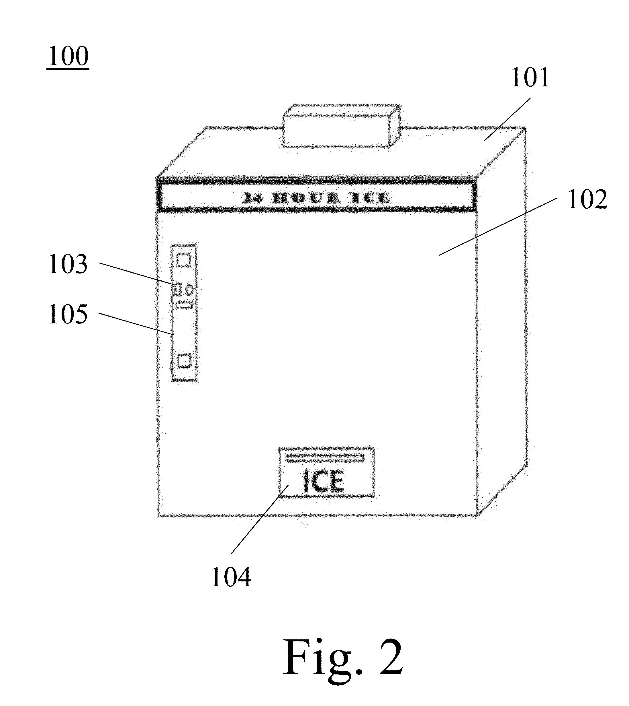
The patent describes a bagged ice vending machine that uses a refrigerated cabinet with an access door for servicing. The machine has money receiver / exchanger plus control electronics and a vended product access door. The front panel or door of the vending machine is opened to allow the ice to be loaded on the conveyor belts as needed. To dispense the product, money is deposited, the drive motor is energized, and the conveyers move in opposite directions to push the ice to the end of the conveyor where it drops to the conveyor below. The product can then be accessed by the customer through the vended product access door. The drive motor will remain energized until the product sensor is satisfied. Overall, the vending machine uses a unique design to efficiently dispense ice to customers.

Problems solved by technology

The downside of these machines is cost and location, which requires water for the manufacturing component of such machines.
Other pre-packaged vending machines are known in the art, but are limited due to the size and weight of prepackaged ice, which is often sold in bags ranging in weight from 5 to 20 lbs.
Current vending machines know in the art are not capable of dispensing multiple sized pre-packed ice bags, or are not capable of being adapted to vending a product the size and weight of a desired bag of ice by the average consumer.
These coolers are inefficient for both sellers and buyers.
Interior coolers are just as inefficient, as they are typically not located near a register, again requiring an employee or the honor system to be used after payment, or a consumer to stack or carry one or more bags in a cart to check out, as the product melts potentially making a mess in the store, and lost value to the buyer.

Method used


Image

  • Bagged Ice Vending Machine
  • Bagged Ice Vending Machine
  • Bagged Ice Vending Machine

Examples


Embodiment Construction

[0026]In the following detailed description of the invention of exemplary embodiments of the invention, reference is made to the accompanying drawings (where like numbers represent like elements), which form a part hereof, and in which is shown by way of illustration specific exemplary embodiments in which the invention may be practiced. These embodiments are described in sufficient detail to enable those skilled in the art to practice the invention, but other embodiments may be utilized and logical, mechanical, electrical, and other changes may be made without departing from the scope of the present invention. The following detailed description is, therefore, not to be taken in a limiting sense, and the scope of the present invention is defined only by the appended claims.

[0027]In the following description, numerous specific details are set forth to provide a thorough understanding of the invention. However, it is understood that the invention may be practiced without these specifi...


PUM


Abstract

A bagged ice vending machine where a drive motor is energized causing conveyors to move, the conveyors are designed to move in opposite directions so that the product will move to the end of that conveyor and drop to the conveyor below, which will force the last bag on the bottom conveyor to fall into the vending chute, activating the ice vended sensor, and slide into the vending hopper, the product can then be accessed by the customer through the vended product access door. A drive chain is configured on each conveyor chain sprocket so that when the drive motor is energized the conveyors will move in opposing directions. This movement indexes the product so that as each item reaches the end of the conveyor it will fall to the conveyor below. Each conveyor will only move the product one position for each product dispense cycle.

Description

CROSS REFERENCE TO RELATED APPLICATIONS[0001]This application claims priority from U.S. Patent Application Ser. No. 61 / 663,167, entitled “Stand and drawing-easel attached to a keyboard to use with mobile electronic devices”, filed on 22 Jun. 2012. The benefit under 35 USC §119e f the United States provisional application is hereby claimed, and the aforementioned application is hereby incorporated herein by reference.TECHNICAL FIELD OF THE INVENTION[0002]The present invention relates generally to vending machines. More specifically, the present invention relates to vending machines for pre-packaged products such as bagged ice.BACKGROUND OF THE INVENTION[0003]The self-service ice industry is one of the fastest growing business opportunities available today. Typically, large vending machines are used that manufacture, store, bag, and dispense purified ice in bags. The downside of these machines is cost and location, which requires water for the manufacturing component of such machines....

Claims


Application Information

Patent Timeline
Patent Type & Authority Applications(United States)
IPC IPC(8): G07F9/10
CPCG07F9/105G07F11/58G07F17/0071
Inventor ABSTON, LESTER
Owner ABSTON LESTER
Learn More