
Transmission Protocol

a technology of transmission protocol and address, applied in the field of information transmission, can solve the problems of limiting the potential of the device, errors in the reading of the address, and the applicability of the device to the address, so as to reduce the time and cost of data transmission

Active Publication Date: 2013-12-19
MARICI HLDG THE NETHERLANDS BV
View PDF9 Cites 7 Cited by
  • Summary
  • Abstract
  • Description
  • Claims
  • Application Information

AI Technical Summary

Benefits of technology

The invention is about using a communication channel where multiple devices can connect and transmit data simultaneously. This requires a system to manage conflicts among data, so each device has its own unique identification number and receives a unique virtual address for efficient data transmission. The technical effect is that it optimizes data transmission times and costs while managing conflicts among devices.

Problems solved by technology

However, an approach of this type also has considerable drawbacks.
This input constitutes a precious resource of the device, because normally a limited number of analogue inputs exists on each device and hence the use of one of them solely for reading the address limits the potential of the device.
The length of the analogue line and the presence of noise can lead to errors in the reading of the address.
Vice versa, when the static address is allocated by means of a digital line, for example by dip-switch, address allocation may be erroneous because of a mistake by the operator in switching the dip-switches.
This entails a waste of resources.
When a device is moved from one housing to another in the rack and it remains lighted during the move, for example because of internal capacities, it retains the previous static address, which is wrong and it comes in conflict with the new device to be inserted in the housing from which it was removed.
If no device is inserted in the previous housing, no conflict situation is created, but if the static address stored in the memory of device that was moved no longer matches its physical position in the rack and the operator may not realise that this anomalous situation exists.
In addition to the addressing problems described above, prior art solutions present additional drawbacks when the need to share information among the devices arises.
Similar problems with sharing information about the temperature in various points of a complex system may occur in the case of battery charges that must be operated according to the measured temperature.
The problem to be confronted in this case stems from the long time required to collect all information that must be shared among the various devices connected to the communication line.
Updating the operating conditions of the devices with this cadence leads to the risk that the devices work for long times on the basis of outdated data that do not match the actual conditions of the system.
In general, if the data on which control of the devices is based change at a faster rate that the data collection rate, the system is not managed correctly.
The higher the number of devices, the longer the time necessary to collect and share the data necessary to manage the individual devices and hence the more severe the problem described above.

Method used


Image

  • Transmission Protocol
  • Transmission Protocol
  • Transmission Protocol

Examples


Embodiment Construction

General Layout of the System and Definition of the Symbols

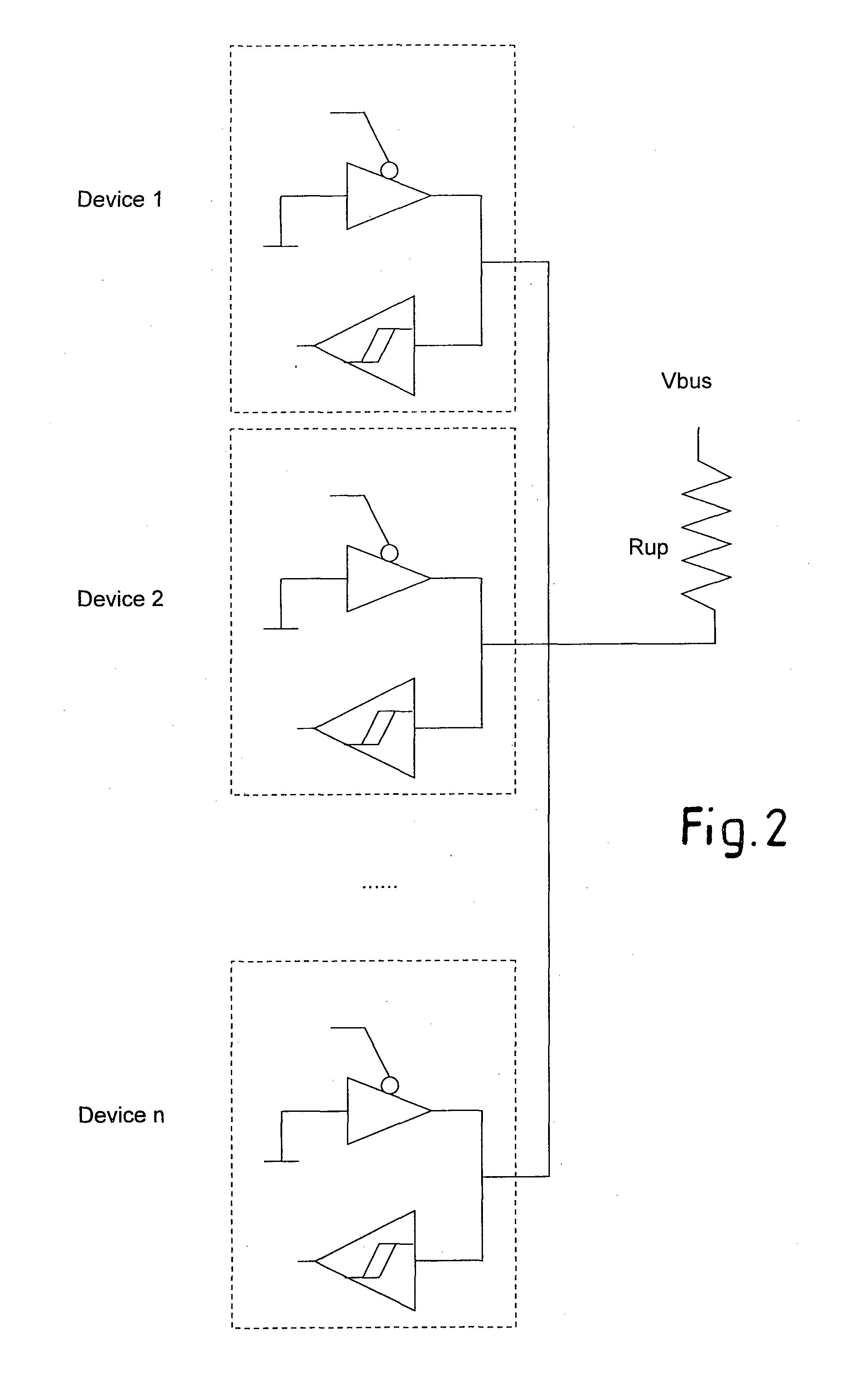
[0035]FIG. 2 shows a portion of a system in which n devices are present, indicated as D1, D2, . . . Di, . . . Dn. Each device Di is a generic electronic device that has to share information through a bus 1 to which it is connected. In the illustrated example, the bus is a single ended bus, but it must be understood that what is described below can also be embodied with a different bus or communication channel, for example a differential bus, i.e. with two wires. The sole requirement the bus must satisfy is that two digital signals must be identifiable on the bus, one strong or dominant (S) and the other one weak or recessive (W). This means that when an attempt is made to transmit two different signals on the bus 1, the strong signal dominates over the weak signal and the strong signal will be present on the bus, whilst the weak signal will be inhibited. That is, the following conditions hold true:

W+W=W

W+S=S

S+S=S

[0036]In t...


PUM


Abstract

A method is described for the transmission of data among devices (D1, D2, . . . Di, . . . Dn) connected to a communication channel (1) through sequences containing at least two symbols, one dominant (“0”) and one recessive (“1”). According to this transmission method, one (DTSG) of the devices connected to the communication channel (1) has the function of time slot generator and it transmits on the communication channel (1) with a transmission frequency (f) a sequence of symbols, each defining a time slot in a sequence of time slots. The sequence of symbols comprises at least a series of recessive symbols (“1”). When one of the devices (Di) has to transmit on the communication channel (1), it generates a sequence of symbols, synchronised with the sequence of time slots generated by the time slot generator device (DTSG) and comprising at least one dominant symbol (“0”).

Description

TECHNICAL FIELD[0001]The present invention relates in general to the transmission of information between devices that share a transmission channel (bus). Each device has its own identification number and it can transmit information to other devices connected to the same bus or communication channel.STATE OF THE ART[0002]There are many applications in which it is necessary to communicate information between electronic devices connected to a bus, for example to send commands and instructions from one device to another or to share information between these devices. For example, when multiple inverters are connected in parallel to supply power on an electric line, it is necessary to balance the various inverters to cause each of them to work substantially under the same conditions, substantially supplying the same current. For this purpose, it is necessary that each device knows at least the working conditions of the inverter that at each instant is supplying the greatest power and its ...

Claims


Application Information

Patent Timeline
Patent Type & Authority Applications(United States)
IPC IPC(8): H04L7/00
CPCH04L12/403H04L7/00H04L25/4902H04L12/4135
Inventor VALIANI, MASSIMOTAZZARI, DAVIDEVERNIA, FILIPPO
Owner MARICI HLDG THE NETHERLANDS BV
Learn More