
Linear solid-state lighting with voltage sensing mechanism free of fire and shock hazards

Active Publication Date: 2013-12-19
ALEDDRA INC
View PDF3 Cites 92 Cited by
  • Summary
  • Abstract
  • Description
  • Claims
  • Application Information

AI Technical Summary

Benefits of technology

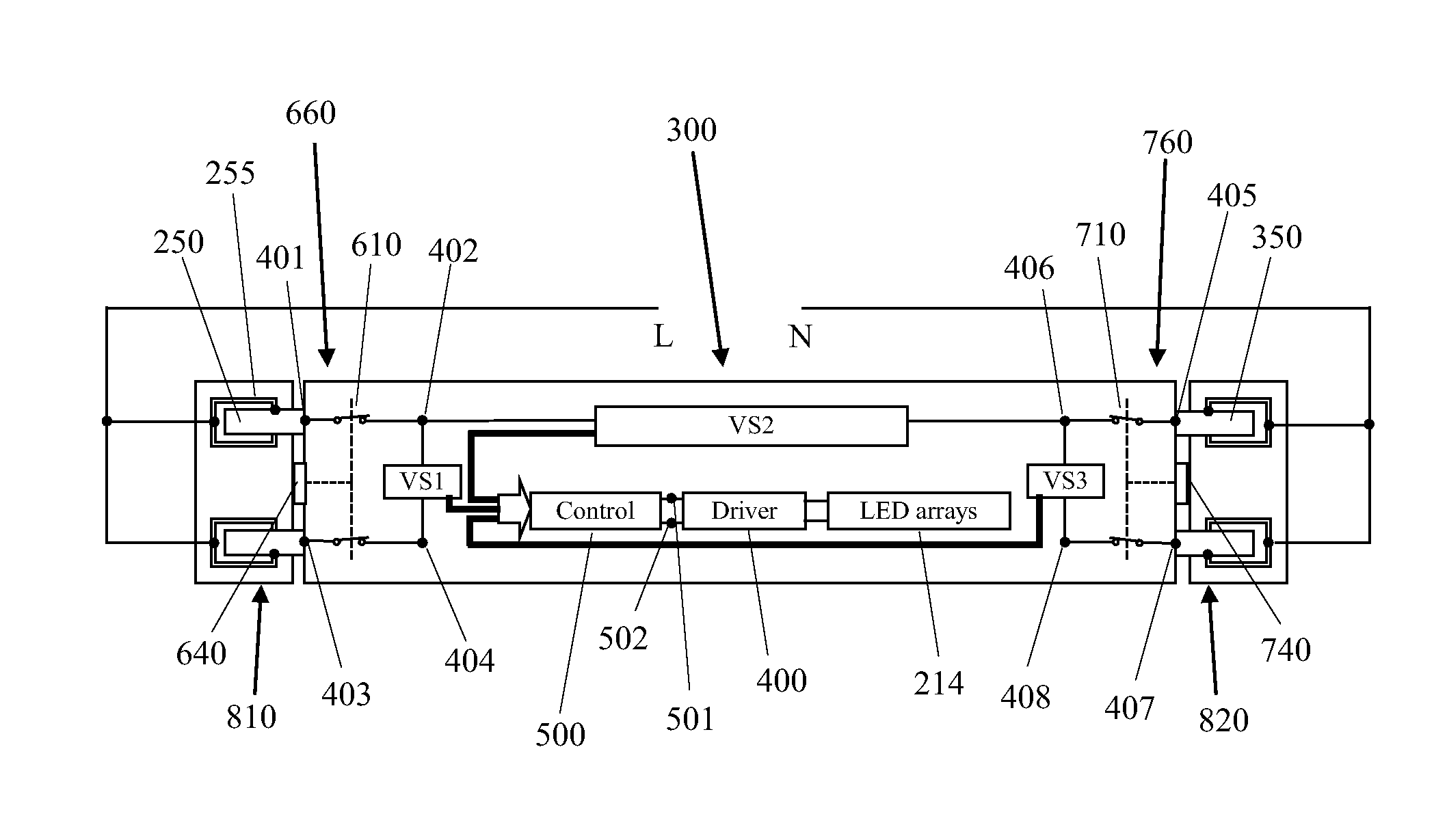
The patent describes a new LED-based solid-state device that can replace fluorescent tubes in existing lighting fixtures. The device has a heat sink, an LED driver, an LED PCB with LED arrays, a lens, and a novel voltage sensing mechanism and control mechanism. These mechanisms allow the LED lamp to detect the type of wiring in the fixture and operate properly with either single-ended or double-ended wiring. The device also uses shock protection switches to buffer the AC power and connect to the LED driver, which eliminates any risk of fire or electrical shock. The technical effect of this invention is to provide a safer and more reliable alternative to fluorescent tubes in lighting fixtures.

Problems solved by technology

This kind of LLT lamps always fails a safety test, which measures through lamp leakage current.
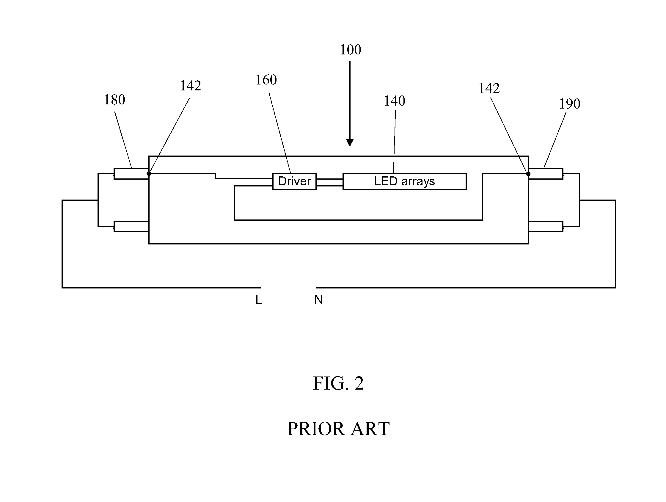
Because the line and the neutral of the AC mains apply to both opposite ends of the tube when connected, the measurement of current leakage from one end to the other consistently results in a substantial current flow, which may present a risk of shock during re-lamping.
Appliances such as toasters and other appliances with exposed heating filaments present the same kind of hazard.
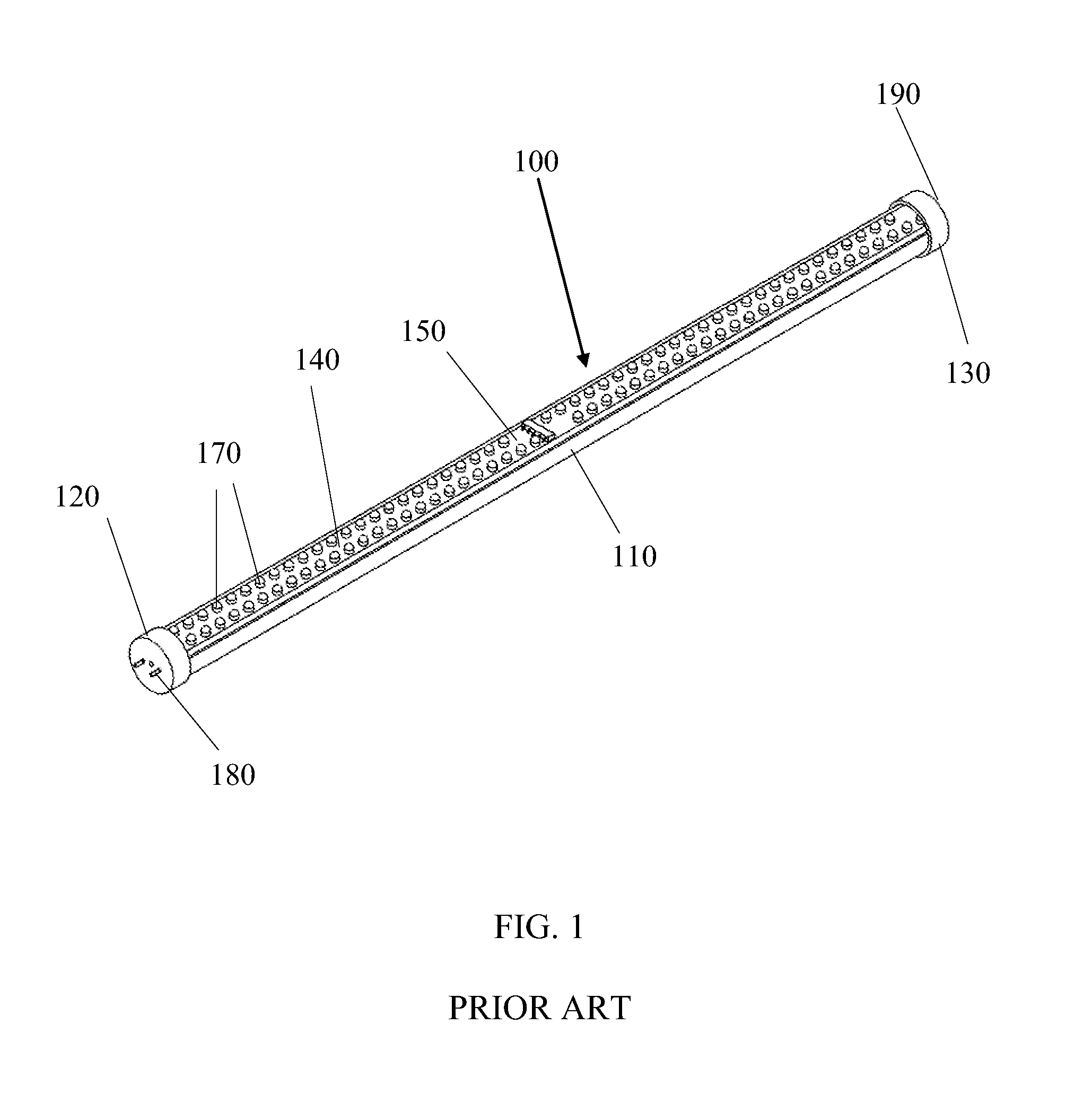
As mentioned, without protection, shock hazard will occur for an LLT lamp, which is at least 2 feet long; it is very difficult for a person to insert the two opposite bi-pins at the two ends of the LLT lamp into the two opposite sockets at two sides of the luminaire fixture at the same time.
At this time, if the person who replaces the LLT lamp 100 touches the exposed bi-pin 190, which is energized, he or she will get electric shock because the current flows to earth through his or her body—a shock hazard.
Almost all the LLT lamps currently available on the market are without any protections for such electric shock.
However, such a single protection approach cannot completely eliminate the possibility of shock risk.
As long as shock risk exists, the consumer product safety remains the most important issue.
In this case, however, the retrofit and rewiring of the existing fixture to enable such LLT lamp may involve two new electrical sockets replacement in the fixture and needs much longer time to complete the rewiring because conventional fluorescent tube is double-ended, and its fixture and lamp holder sockets are wired in a double-ended manner.
The new sockets, rewiring, and installation costs together will be too high for consumers to replace conventional fluorescent tubes economically.
But this introduces shock and fire hazards.
This definitely will burn the connections on the bi-pin, possibly causing fire, and trip the circuit breaker.
Due to this potential shock and fire risk for this kind of LLT lamp modification used with an existing fluorescent tube fixture, UL requires that the lamp base bi-pin used for mechanical support only not be interconnected or connected to dead metal parts of the lamp base.
Similar hazards occur for double-ended lamps.
Such lamps will never pass UL leakage current test and present the shock risk during re-lamping, as mentioned above.
In addition, such non-UL compliant LLT lamps have their bi-pins internally connected.
Furthermore, because LLT lamps have a very long service life, consumers who do not know single-ended and double-ended configurations may try to install their LLT lamps in another fixture with unknown wiring configuration several years later while original installation / wiring instructions may not be found.
In this case, there exist fire and shock hazards.
This presents a shock hazard.
However, such lamps are non-operable because no power supplies to the driver when used with single-ended fixtures.
Even worse, when the two adjacent pins of the bi-pin on either one of the two ends in the double-ended LLT lamp are abnormally interconnected, the lamps may present fire hazard as mentioned above.

Method used


Image

  • Linear solid-state lighting with voltage sensing mechanism free of fire and shock hazards
  • Linear solid-state lighting with voltage sensing mechanism free of fire and shock hazards
  • Linear solid-state lighting with voltage sensing mechanism free of fire and shock hazards

Examples


Embodiment Construction

[0028]Misapplications of power supply connections for LLT lamps that substitute for linear fluorescent lamps are the main causes of fire and electric shock hazards today, where the LLT lamps are incorrectly connected to a supply source, the lamp base is either inserted incorrectly into a lamp holder or inserted into a lamp holder not intended for the lamp, or a lamp is connected to lamp holders with supply connections that do not match the lamp configuration. All of these misapplications may result in fire and shock hazards.

[0029]To completely remove these hazards from LLT lamps, manufacturers need to ensure at first no electrically shorted ends in either single-ended or double-ended LLT lamps. For double-ended LLT lamps, double protection switches on both ends of the LLT lamps must be used without compromise. For single-ended LLT lamps, consumers may find them difficult to use because there is a chance that the LLT lamps cannot be lighted up after installation due to the fact that ...


PUM


Abstract

A linear light-emitting diode (LED)-based solid-state lamp using a novel voltage sensing and control mechanism operates normally in both single-ended and double-ended luminaire fixtures. The voltage sensing and control mechanisms automatically detect supply source configuration in the fixture and make proper management so that the linear LED lamp works in any fixtures without operational uncertainty or risk of fire. When used with shock protection switches on the two lamp bases at two opposite ends, the universal lamp fully protects a person from possible electric shock during initial installation and re-lamping.

Description

BACKGROUND OF THE INVENTION[0001]1. Field of the Invention[0002]This invention relates to linear light-emitting diode (LED) lamps that adopt novel voltage sensing and control mechanisms and thus work with any linear luminaire fixtures configured as single-ended or double-ended, and more particularly to a universal, shock and fire hazard-free linear LED tube lamp with a shock-protection mechanism.[0003]2. Description of the Related Art[0004]Solid-state lighting from semiconductor light-emitting diodes (LEDs) has received much attention in general lighting applications today. Because of its potential for more energy savings, better environmental protection (with no hazardous materials used), higher efficiency, smaller size, and longer lifetime than conventional incandescent bulbs and fluorescent tubes, the LED-based solid-state lighting will be a mainstream for general lighting in the near future. Meanwhile, as LED technologies develop with the drive for energy efficiency and clean te...

Claims


Application Information

Patent Timeline
IPC IPC(8): F21V23/04F21V23/00
CPCF21V23/0442F21V25/00F21Y2101/02F21K9/17H05B33/0803Y02B20/341F21Y2115/10F21K9/278Y02B20/30H05B47/26
Inventor HSIA, CHUNGHOSHEN, PAI-SHENG
Owner ALEDDRA INC
Learn More