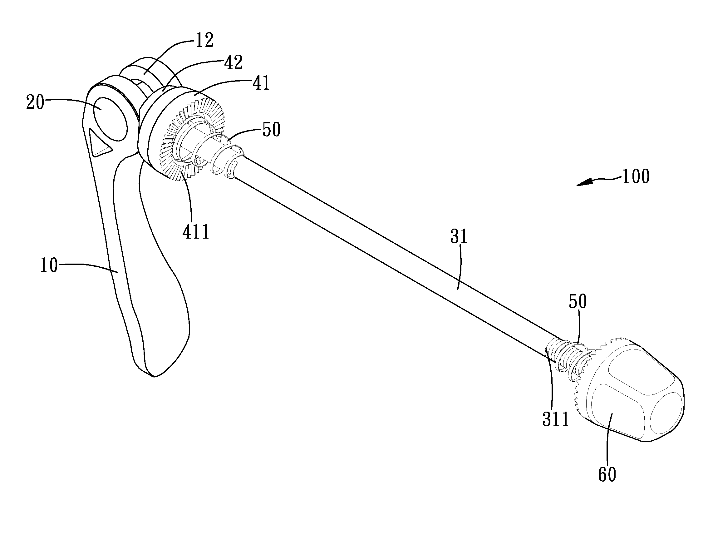
Quick-release device for use on a bicycle

Inactive Publication Date: 2013-12-19
CHANG CHIN CHAO
View PDF13 Cites 19 Cited by
  • Summary
  • Abstract
  • Description
  • Claims
  • Application Information

AI Technical Summary

Benefits of technology

The invention is a better quick-release device that reduces vibrations while riding a bicycle. The device has a special connection between the axle and the shaft, which increases safety during riding. The head of the device is securely attached to the shank, which prevents it from moving due to virelations. The technical effects of this invention are improved safety and stability while riding a bicycle.

Problems solved by technology

However, the bicycle may cause vibration during riding passing a rough ground.
It is very dangerous when riding the bicycle.

Method used


Image

  • Quick-release device for use on a bicycle
  • Quick-release device for use on a bicycle
  • Quick-release device for use on a bicycle

Examples


second embodiment

[0027]With reference to FIGS. 6 and 7 that shown the quick-release device (200) in accordance with the present invention, in this embodiment, the shank (31) further includes at least one annular groove (312) defined therein for positioning a distal end (51) of the at least one spring (50).

third embodiment

[0028]With reference to FIGS. 8 and 9 that show the quick-release device (300) in accordance with the present invention, in this embodiment, the axle (20) further includes two threaded holes (23) respectively centrally defined in two opposite sides of the axle (20), wherein each threaded hole (23) laterally communicates with the indentation (22) and has a bolt (70) screwed therein. The bolts (70) are rotated and extend to secure the head (32) of the shaft (30) for promoting the connection between the axle (20) and the shaft (30).


PUM


Abstract

A quick-release device for use on a bicycle includes a lever, an axle rotatably received in the lever, a shaft extending through the axle, a force device sleeved on the shaft, at least one spring sleeved on the shaft and a nut screwed onto the shaft. The axle includes an indentation defined therein and a first abutment formed on a bottom of the indentation. The shaft includes a shank and a head formed one end of the shank such that a second abutment is formed between the shank and the head. The head is received and engaged in the indentation such that the shank can not be rotated relative to the axle and the connected of the quick-quick device in promoted.

Description

BACKGROUND OF THE INVENTION[0001]1. Field of the Invention[0002]The present invention relates to a quick-release device, and more particularly to a quick-release device that is provided for used on a bicycle.[0003]2. Description of Related Art[0004]A conventional quick-release device (1) for use on a bicycle in accordance with the prior art shown in FIG. 1 comprises a threaded rod (2), two springs (3) respectively sleeved on the threaded rod (2) and a nut (4) screwed onto a first end of the threaded rod (2). A presser (5) and a block (6) are sequentially sleeved on the threaded rod (2), wherein the two springs (3) respectively abut against the nut (4) and the presser (5). A lever (8) is pivotally connected to a second end of the threaded rod (2). The lever (8) includes an eccentrical hole (7) defined in a pivot end thereof to form a cam (not numbered), wherein the cam abuts against the block (6). An axle (9) is pivotally received in the eccentrical hole (7) and the threaded rod (2) ...

Claims


Application Information

Patent Timeline
IPC IPC(8): B60B35/04
CPCB60B27/026
Inventor CHANG, CHIN-CHAO
Owner CHANG CHIN CHAO
Why Eureka
Try Eureka