
System and algorithm for multipath mitigation

a multi-path mitigation and algorithm technology, applied in the field of wireless communication, can solve problems such as signal distortion and reduction of received signal energy

Active Publication Date: 2013-12-12
BAE SYST INFORMATION & ELECTRONICS SYST INTERGRATION INC
View PDF12 Cites 12 Cited by
  • Summary
  • Abstract
  • Description
  • Claims
  • Application Information

AI Technical Summary

Benefits of technology

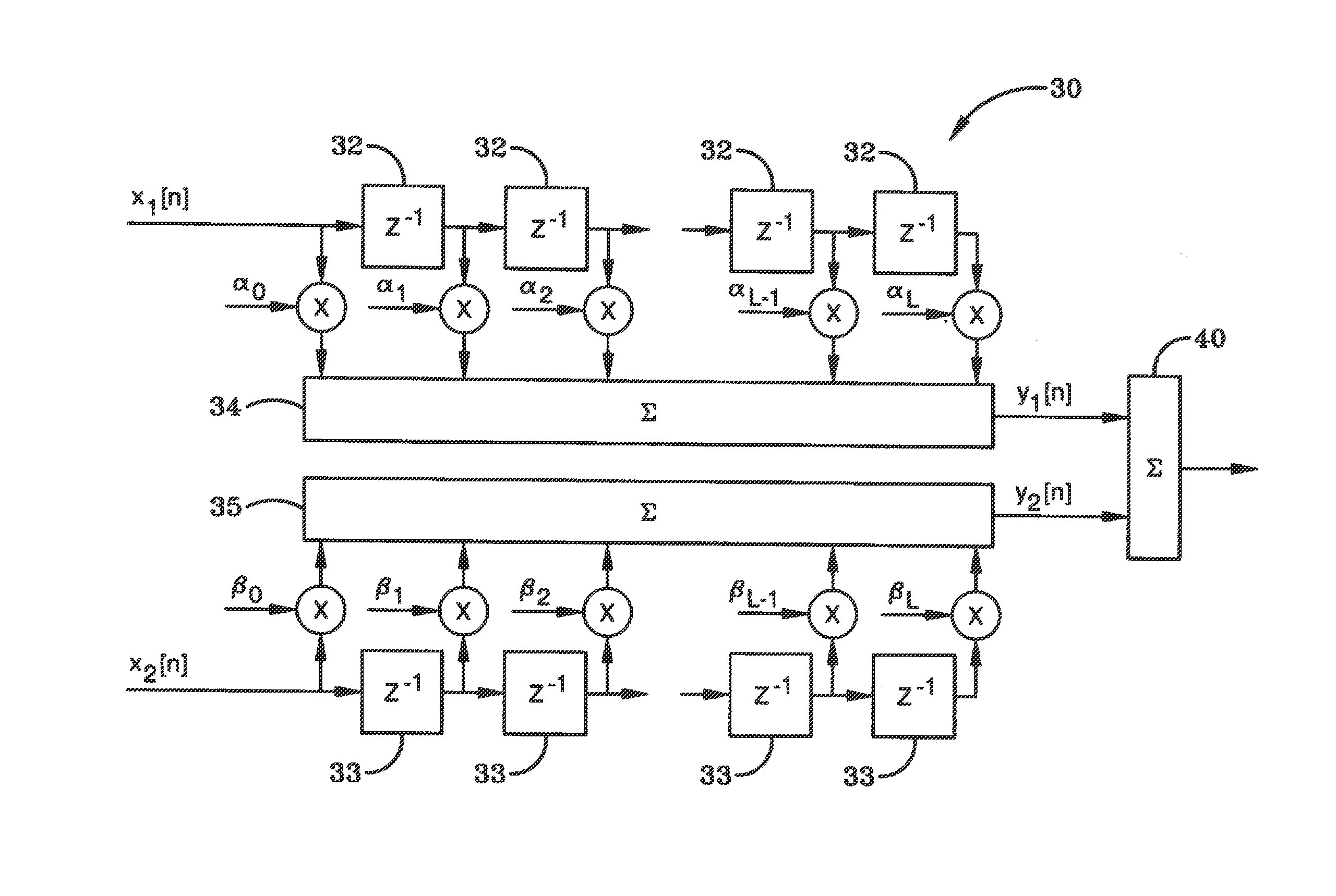
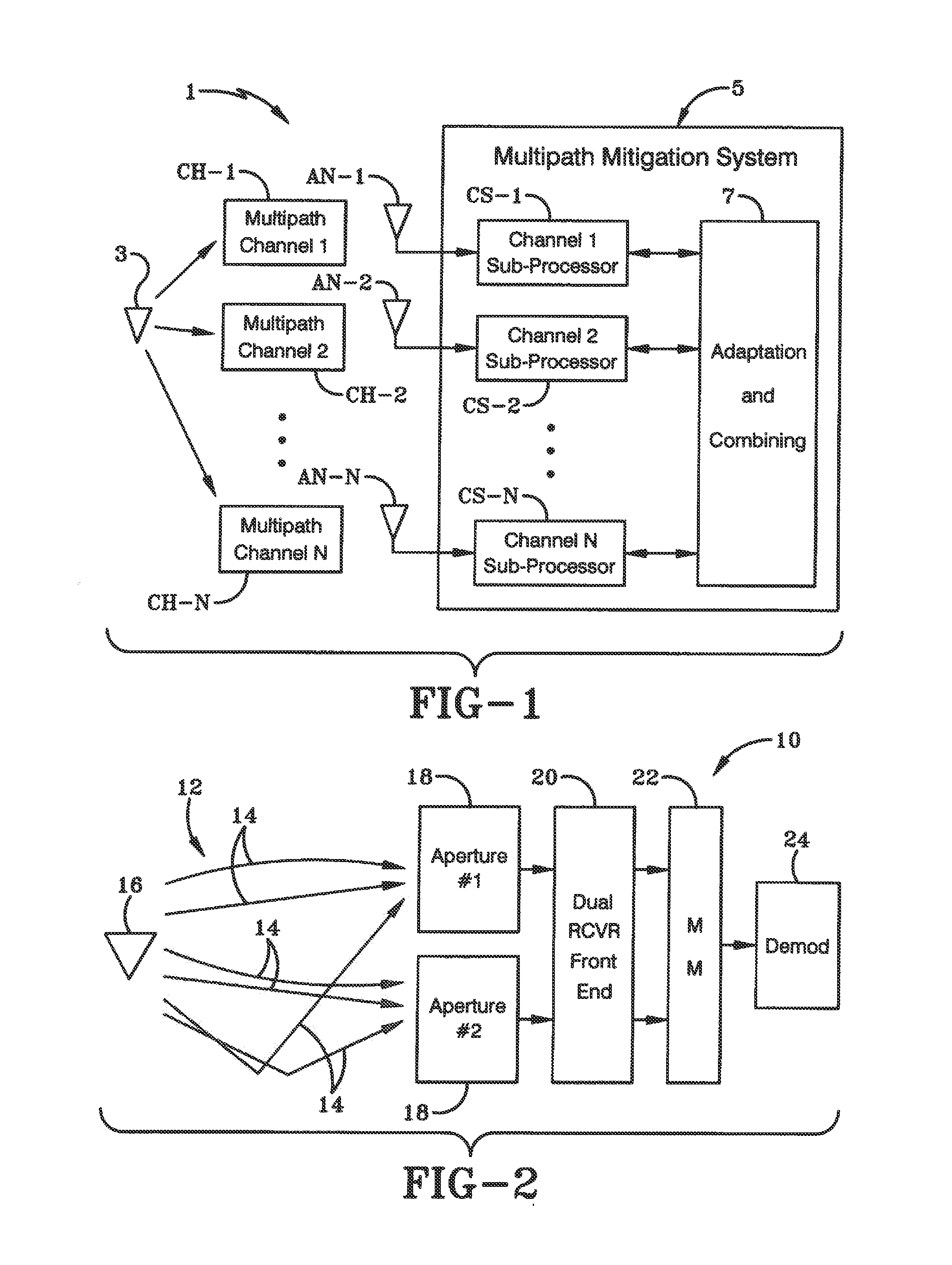
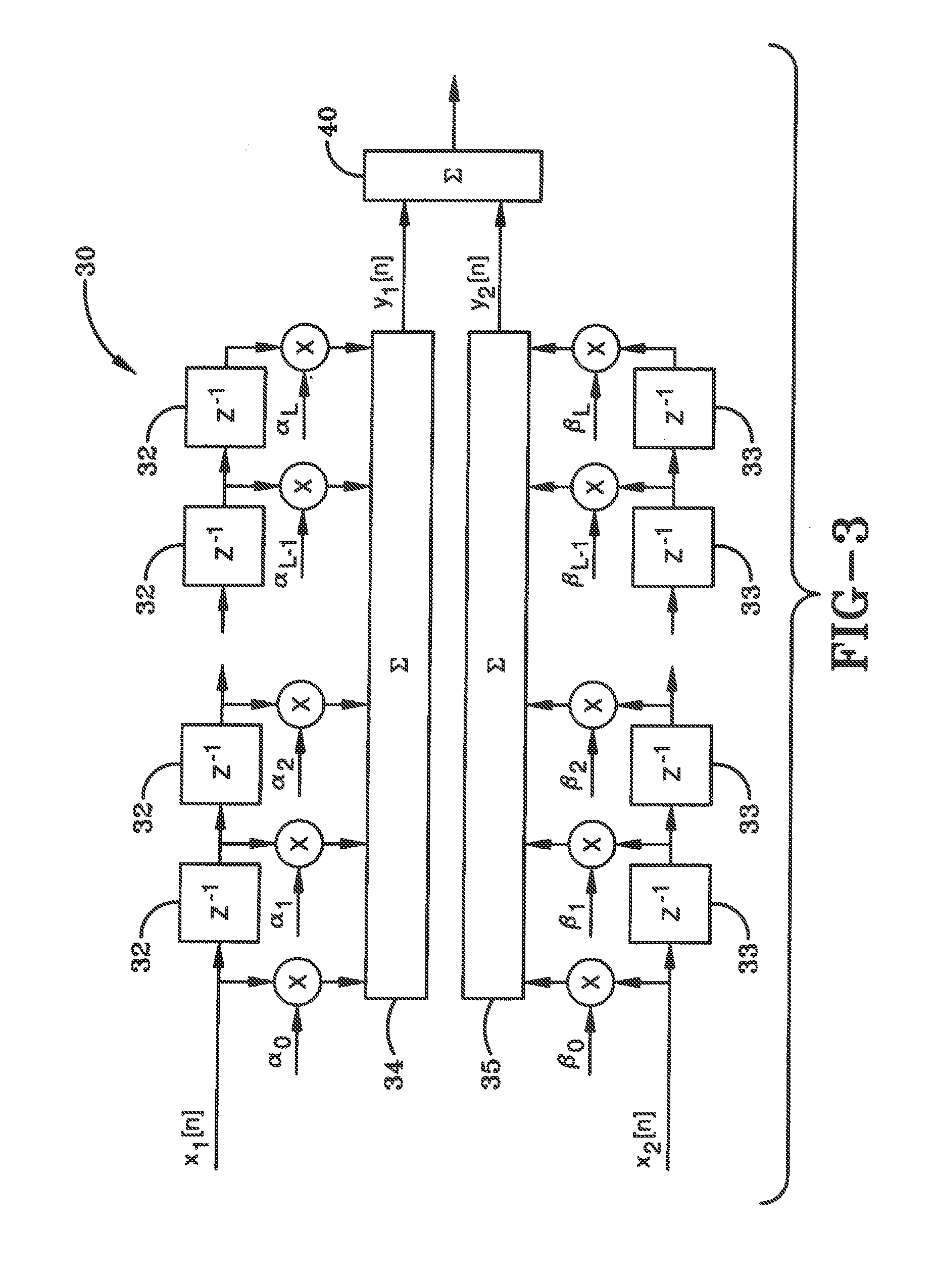
The preferred embodiment of this invention is a method for optimally combining multi-path signals. The method involves receiving two signals that travel different paths and have different distortion. The signals are then combined using a weighting system that maximizes the signal-to-noise ratio. The combined signal has less degradation than the original signals. The system includes a first channel sub-processor logic, a second channel sub-processor logic, an objective function, and adaption and combining logic. The system applies a weight value to each signal to produce a weighted signal, which is then linearly combined to produce the combined signal. The technical effect of this invention is significant improvement in signal quality and reduced signal degradation in a multi-path signal environment.

Problems solved by technology

This superposition can result in partial cancellation of the received field at the antenna and thus a reduction in received signal energy.
In addition, when the respective components of the multipath ensemble arrive at the antenna with distinct time delays (that is, having traversed different path lengths and thus having different propagation times), the components combine in a manner that may result in distortion of the signal.

Method used


Image

  • System and algorithm for multipath mitigation
  • System and algorithm for multipath mitigation
  • System and algorithm for multipath mitigation

Examples


Embodiment Construction

[0022]Before referring to specific figures below, the preferred embodiment of an algorithm to more accurately receive and detect multipath signals will be described. When there are multiple receiving antennas available for reception of the signal of interest there is an opportunity to realize a significant improvement in system performance by optimally combining the respective antenna outputs. It is customary to refer to the respective receiving antennas and corresponding sub-channels (propagation paths) by which energy reaches them as diversity “branches” in recognition of the fact that the impairment (fading or dispersion) on the different branches is usually uncorrelated from branch to branch, or at least not strongly correlated, resulting in a diversification of the signal quality that reduces the probability of a simultaneously poor signal condition at all branch outputs. More specifically, when the multiple antenna outputs exhibit distinct fading characteristics, as is usually...


PUM


Abstract

A system and method for optimally combining multi-path signals is presented. A first signal is received that traveled a first path from a transmitter to a receiving location and a second signal is received that traveled a different second path from the transmitter to the same receiving location. The paths are different so that the first and second signals contain the same signal data but the first signal has a first distortion that is different than a second distortion in the second signal. According to an objective function, the method adaptively generates a first weight value and a second weight value. The first and second weight values are applied to the respective first and second signals to produce respective first and second weighted signals. The first and second weighted signals are linearly combined producing a combined signal with a combined signal degradation.

Description

CROSS REFERENCE TO RELATED APPLICATION[0001]This application claims priority from U.S. Provisional Application Ser. No. 61 / 689,757, filed Jun. 11, 2012; the disclosure of which is incorporated herein by reference.BACKGROUND[0002]1. Field of Invention[0003]The current invention relates generally to apparatus, systems and methods for communicating. More particularly, the apparatus, systems and methods relate to wireless communication. Specifically, the apparatus, systems and methods provide for improved reception of signals by analysing two or more signals at the same time and dynamically weighting the signals to product a better resulting signal.[0004]2. Description of Related Art[0005]In digital radio communication systems a signal is transmitted from a transmitting antenna to a receiving antenna via a channel, which channel comprises open space generally containing objects such as the earth and its topographic features (mountains, oceans) as well as buildings, vehicles and other ma...

Claims


Application Information

Patent Timeline
Patent Type & Authority Applications(United States)
IPC IPC(8): H04B1/10
CPCH04B1/1081H04L25/03057H04L2025/03484H04L2025/03605H04L2025/03681
Inventor LOMP, GARY R.
Owner BAE SYST INFORMATION & ELECTRONICS SYST INTERGRATION INC
Learn More