Crevice tool for vacuum cleaners

a vacuum cleaner and crevice technology, applied in the field of crevice tools for vacuum cleaners, can solve the problem that the use of tools is extremely limited in narrow spaces, and achieve the effect of efficient removal of dir

Inactive Publication Date: 2013-12-12
SCHWARTZ MICHAEL N
View PDF5 Cites 29 Cited by
  • Summary
  • Abstract
  • Description
  • Claims
  • Application Information

AI Technical Summary

Benefits of technology

[0007]The present invention provides an effective vacuum attachment for efficiently removing dirt, dust, and other debris from narrow spaces typically found in, but not limited to, homes, offices, and other buildings which contain multiple numbers of said narrow spaces. The angle at which the attachment is formed will enable the tool to be used from a different angle of approach than being in direct parallel to the narrow space in need of vacuuming. The angle may be between about 0° to 60°. Such as standing in front of a piece of furniture, sliding the tool in a back and forth motion, as opposed to needing to get down on the floor; sliding the tool between a piece of furniture and a wall also without needing to move the furniture for putting the vacuum hose against the wall.

Problems solved by technology

This tool is extremely limited in its use for vacuuming in narrow spaces, in that it will only remove debris located directly in front of the suction slot.

Method used


Image

  • Crevice tool for vacuum cleaners
  • Crevice tool for vacuum cleaners
  • Crevice tool for vacuum cleaners

Examples


Embodiment Construction

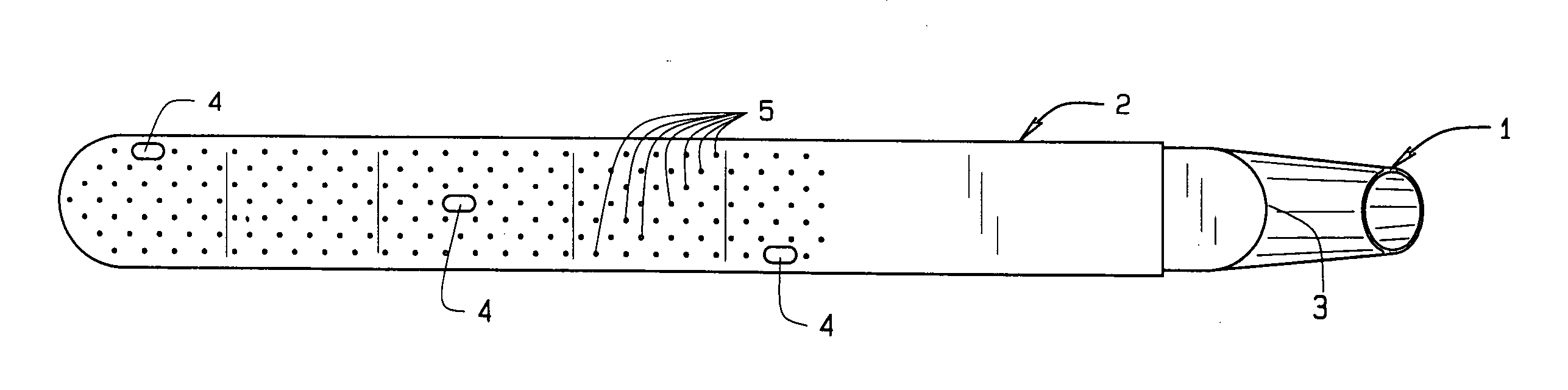
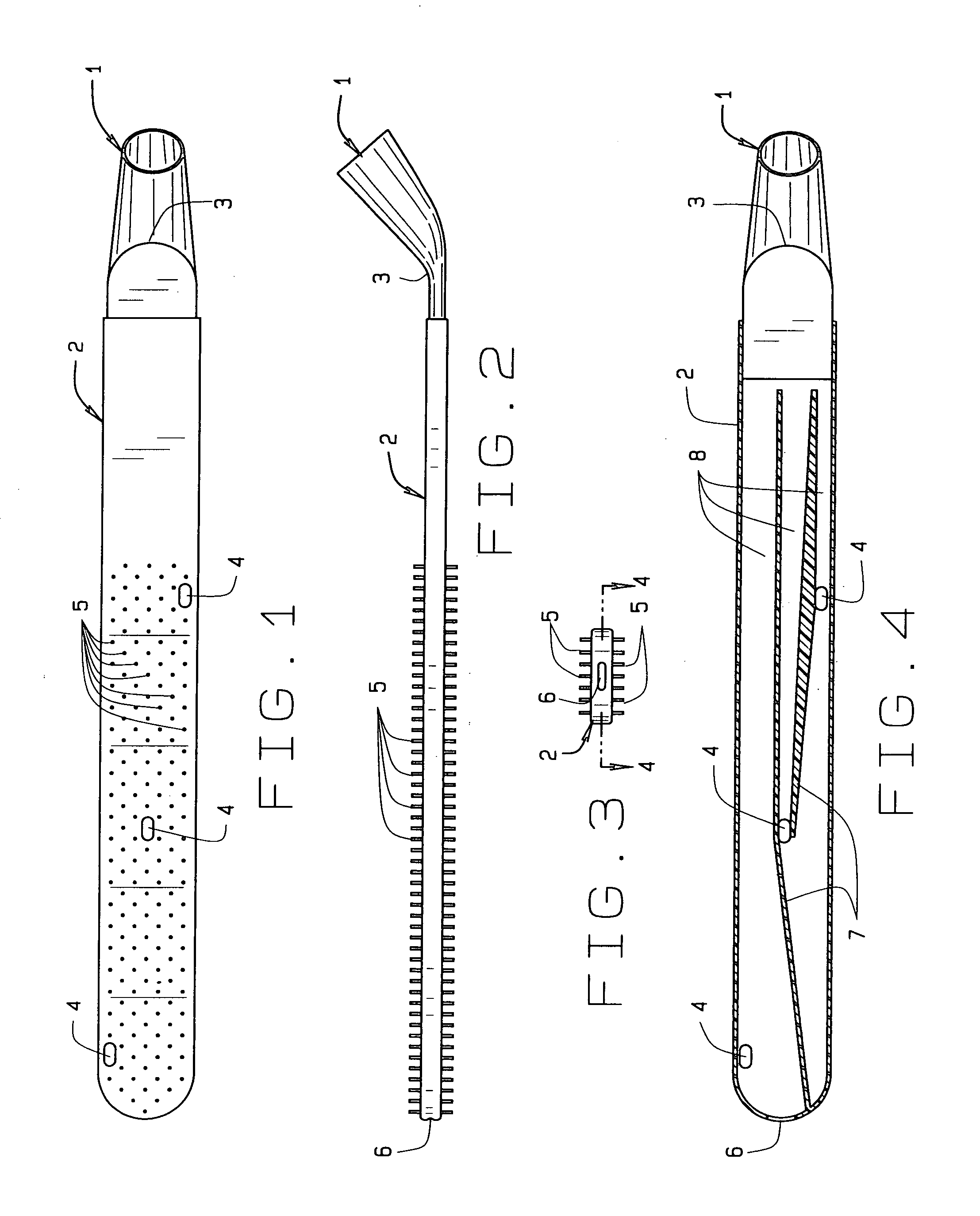
[0034]FIG. 1 shows the top view of the crevice tool where it can be seen that there is a tapered male end 1 at one end, transitioning into the flat air chamber or of the crevice tool 2, through which debris laden air will pass from the suction slots 4 and 6, through the tapered male end 1 of the tool, and into the vacuum cleaner to which it is attached.

[0035]FIG. 2 illustrates the nubs 5 protruding from the top and bottom surfaces of the crevice tool 2, which, when raked over a debris ridden surface, will dislodge said debris and, using the air movement caused by the vacuum cleaner through suction transferred to the suction slots 4 and 6, will become air born in the immediate vicinity from where the debris particles were dislodged, causing said particles to move into the air chambers and consequently be removed from the areas being vacuumed.

[0036]FIG. 3 illustrates the air slit 6 at the end of the invention and an end view of a support rib 7 extending lengthwise inside the air chamb...


PUM


Abstract

The present invention refers to a crevice tool for vacuum cleaners as a singular component, comprising a socket transitioning into a long, flat air chamber, at an angle of approximately 45 degrees, wherein the air chamber (wand) incorporates both air suction slots and protruding nubs on both the top and bottom of the tool, and lateral slits in the end opposite the socket end. The various components of the crevice tool may be fabricated into kit form, and may include an adaptor, an extension, and a paw like terminal end, that can be used for removing any debris from tight areas.

Description

CROSS REFERENCE TO RELATED APPLICATION[0001]This non-provisional patent application claims priority to the provisional patent application having Ser. No. 61 / 689,727, filed on Jun. 12, 2012.FIELD OF THE INVENTION[0002]The present invention refers to a crevice tool for vacuum cleaners that comprises a socket extending into a flat air channel.BACKGROUND OF THE INVENTION[0003]Crevice tools for vacuum cleaners are already known in the art. One example of these already known tools is shown in U.S. Pat. No. 4,694,529, filed on May 6, 1986. FIG. 1 shows the referenced tool, where one can see that the only suction openings are located near and at the end of the tool. Therefore, as the tools are inserted into a narrow opening in need of cleaning typical debris, the tool will suck only that debris which lies directly at the opening.[0004]Another example of these already known tools is the typical, rigid plastic, tubular vacuum cleaner, while the opposing end is an angled opening in a rectangul...

Claims


Application Information

Patent Timeline
Patent Type & Authority Applications(United States)
IPC IPC(8): A47L9/02
CPCA47L9/02
Inventor SCHWARTZ, MICHAEL N.
Owner SCHWARTZ MICHAEL N
Why Eureka
Try Eureka