
System for attaching a turbojet engine spinner

a turbojet engine and spinner technology, which is applied in the direction of machines/engines, liquid fuel engines, combustion air/fuel air treatment, etc., can solve the problems of increasing the drag of the turbine engine, fuel consumption, and encouraging aerodynamic losses, so as to reduce the aerodynamic disturbance

Active Publication Date: 2013-12-05
SN DETUDE & DE CONSTR DE MOTEURS DAVIATION S N E C M A
View PDF1 Cites 6 Cited by
  • Summary
  • Abstract
  • Description
  • Claims
  • Application Information

AI Technical Summary

Benefits of technology

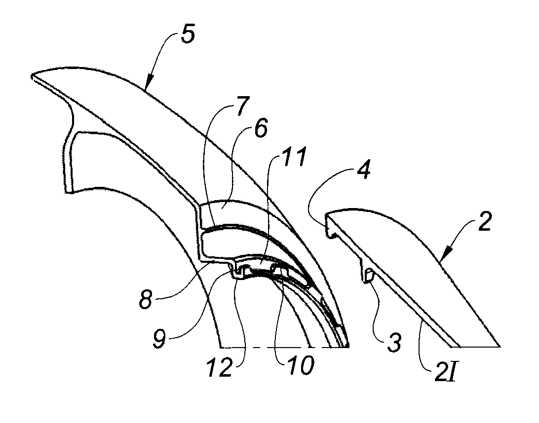
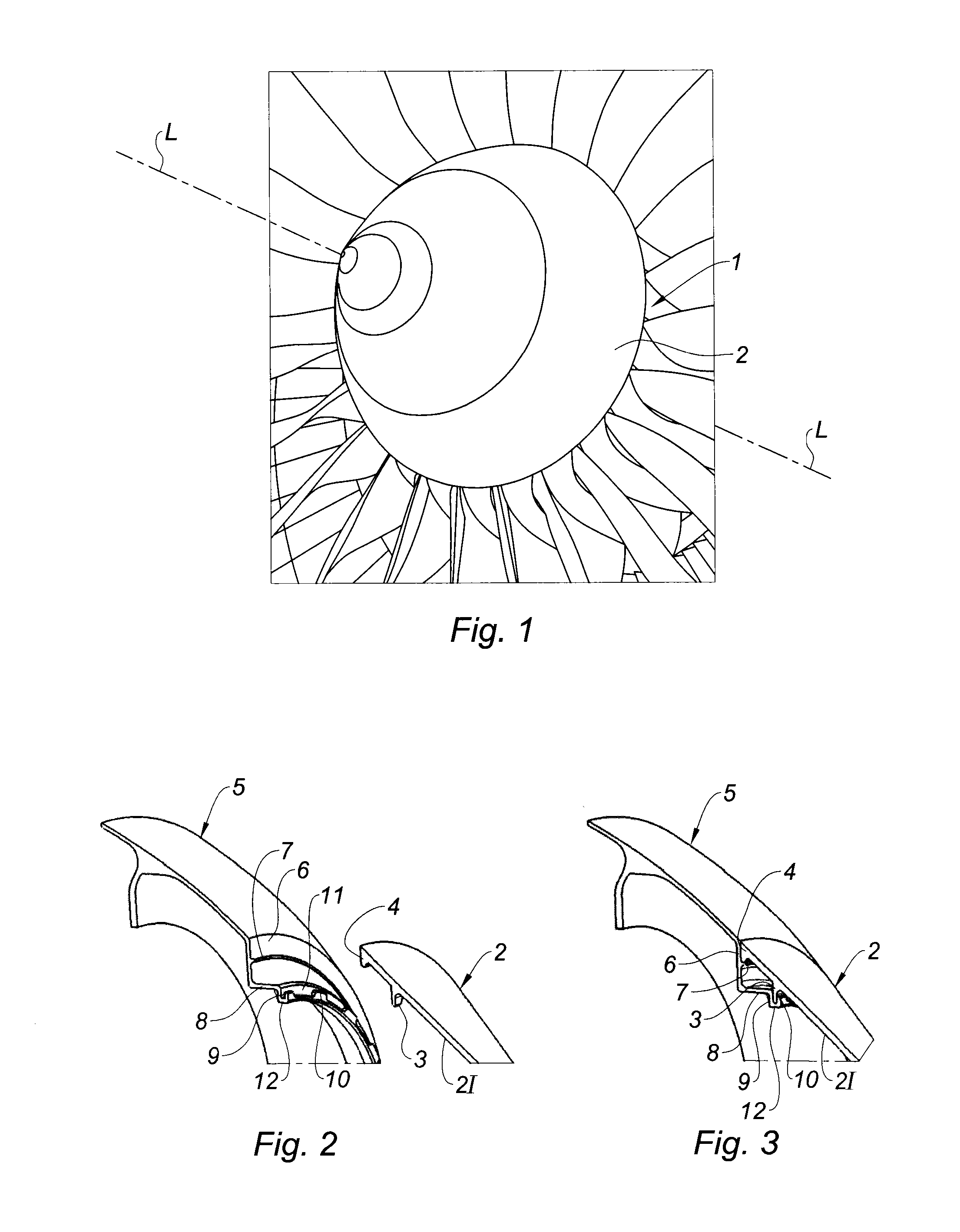
[0009]It is an object of the present invention to remedy these disadvantages and, notably, to reduce the aerodynamic disturbances to the air stream flowing over the spinner of a turbine engine while at the same time making it easier for said spinner to be fitted to and removed from said engine.
[0011]Thus, by virtue of the invention, the axial clamping—which entails recourse to a plurality of axially directed screws—is replaced with a dog clutch attachment that holds the spinner axially with respect to the corresponding rotor. Use of a dog clutch means there is no longer any need for a plurality of axial screws (or the creation of the corresponding spot faces), thus making the fitting and removal of the spinner substantially easier, leading to a reduction in the maintenance time for the corresponding turbomachine. Further, by virtue of the invention, the outer surface of the spinner is perfectly, or almost, smooth because there are no axially directed screws or associated spot faces. The aerodynamic disturbances of the gas stream flowing over the spinner are therefore appreciably reduced, increasing turbomachine performance.
[0017]Thus, by virtue of the invention, the spinner of the upstream rotor can be fitted and removed via two operations which are simple and require no special-purpose and expensive tooling, namely:

Problems solved by technology

However, despite these precautions, the screw head and the spot faces made in the spinner are still “visible” to the incoming air stream.
Further, because of the axial orientation of the screws (i.e. because they are oriented in the same direction as the incoming air stream), the frontal surface of the screws visible to the air stream is at a maximum, encouraging aerodynamic losses and increasing the drag of the turbine engine and, therefore, the fuel consumption thereof.
Moreover, recourse to a plurality of screws for axially clamping the spinner to the fan rotor means that it takes a great deal of time to fit and to remove the spinner.
The use of this special-purpose tooling increases the time that the operations take and, therefore, increases aircraft maintenance costs.

Method used


Image

  • System for attaching a turbojet engine spinner
  • System for attaching a turbojet engine spinner
  • System for attaching a turbojet engine spinner

Examples


first embodiment

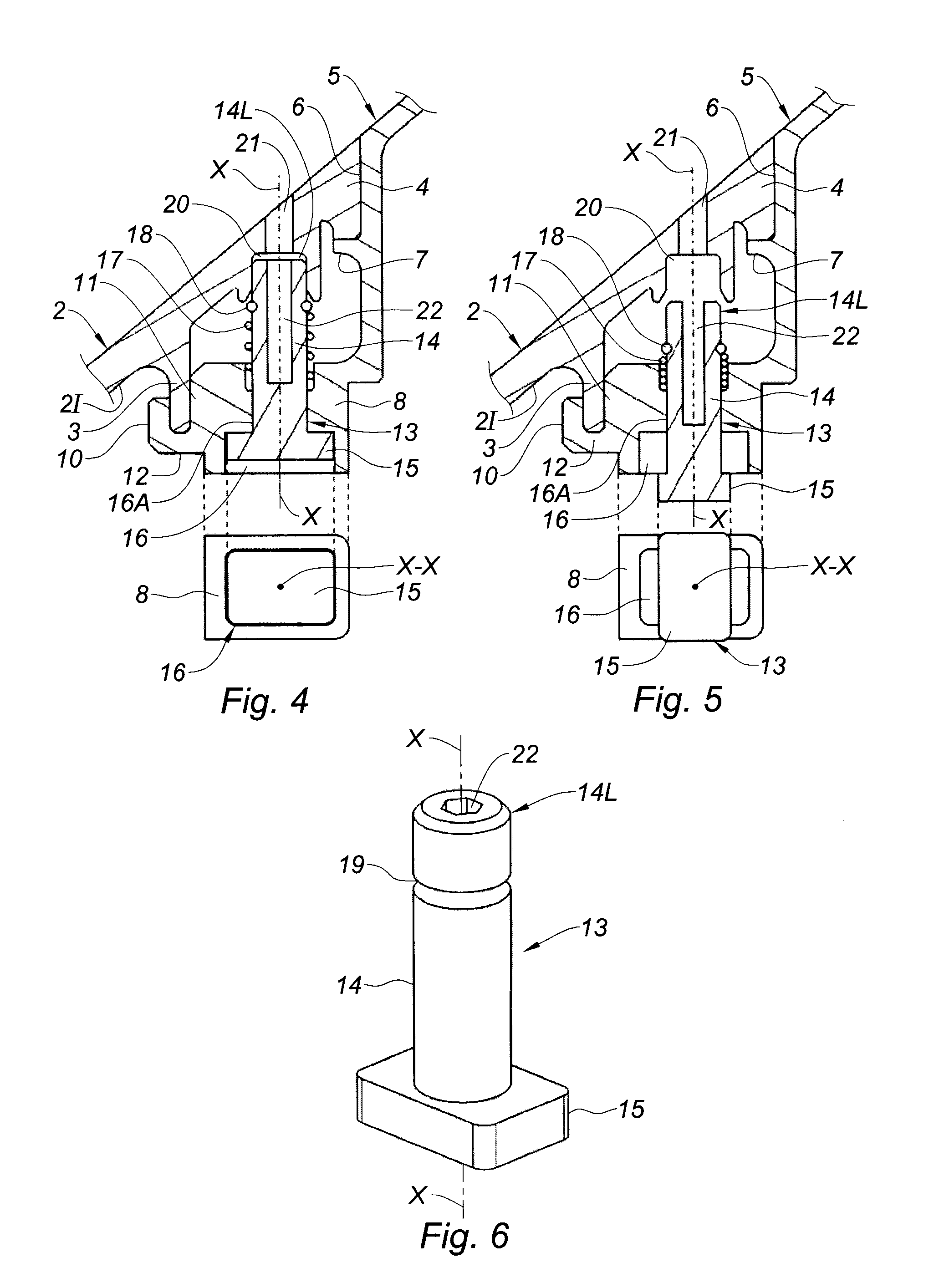
[0045]Moreover, in a first embodiment according to the present invention, and illustrated in FIGS. 4 to 6, the rotation-proofing means comprise two rotation-proofing pegs 13 which are diametrically opposed so as to maintain the dynamic balance of the fan rotor 1, and which are able, independently of one another, to occupy at least one of the following two positions:[0046]a locked position (FIG. 4) in which the spinner 2 is prevented from rotating with respect to the fan rotor 1; and[0047]an unlocked position (FIG. 5) in which the spinner 2 is allowed to rotate with respect to the fan rotor 1.

[0048]As FIGS. 4 to 6 show, each rotation-proofing peg 13 comprises a cylindrical shank 14, of axis X-X, and a head 15 secured to one longitudinal end of the shank 14.

[0049]In this first example, the head 15 of the peg 13 is of flat rectangular shape. When a rotation-proofing peg 13 is in the locked position (FIG. 4), its head 15 is able to enter a corresponding main housing 16 formed in the wal...

second embodiment

[0073]In a second embodiment according to the invention and depicted in FIGS. 7 to 9, the rotation-proofing means comprise two rotation-proofing pegs 23 which are diametrically opposed and able, independently of one another, to occupy at least a locked position (FIG. 7) and an unlocked position (FIG. 8). Each rotation-proofing peg 23 is formed of a cylindrical shank 24 of axis X-X, and of a head 25 secured to one longitudinal end of the shank 24.

[0074]In this second example, the head 25 of the pegs 23 is in the form of a trapezoidal prism. When a rotation-proofing peg 23 is in the locked position (FIG. 7), its head 25 is inserted in a main housing 26 formed for that purpose in the flange 5 and the spinner 2 once these two have been joined together. In other words, the main housing 26 is defined when the spinner 2 is mounted on the flange 5 and correctly angularly oriented in relation thereto. That portion of the main housing 26 that is made in the flange 5 corresponds to a recess ma...


PUM


Abstract

According to the invention, the upstream rotor of a turbomachine, of longitudinal axis L-L, comprising a spinner (2) coaxial with the axis L-L and which is attached removably to the upstream end of the rotor (1) by attachment means, is characterized in that the said attachment means comprise a dog clutch (3, 9, 10) and rotation-proofing means preventing the spinner (2) from rotating with respect to the rotor (1).

Description

BACKGROUND OF THE INVENTION[0001]The present invention relates to turbomachines and, more particularly, to an upstream rotor of such turbomachines.[0002]Although the present invention is particularly well suited to aircraft turbine engines, it is not, however, restricted to that aeronautical application.[0003]In a known way, a turbine engine comprises a gas generator formed of one or more sets of rotors rotating about a common axis. Each set, known as a spool, is made up of a compressor and of a turbine which are connected by a shaft or a drum and positioned one upstream of and the other downstream of a combustion chamber in relation to the flow of gas streams through the turbine engine. Associated with this gas generator is a fan that it drives. When the fan rotor is positioned at the front of the turbine engine, the air inlet of the generator is situated downstream of this rotor.[0004]Moreover, it is known that the fan rotor comprises a spinner which forms the most upstream rotati...

Claims


Application Information

Patent Timeline
IPC IPC(8): F02C7/04
CPCF02C7/04F01D5/3015F01D5/06F05D2220/36F05D2260/33Y02T50/60F01D5/02
Inventor PATSOURIS, EMMANUELBART, JACQUES RENE
Owner SN DETUDE & DE CONSTR DE MOTEURS DAVIATION S N E C M A
Learn More