Developing device and image forming apparatus
- Summary
- Abstract
- Description
- Claims
- Application Information
AI Technical Summary
Benefits of technology
Problems solved by technology
Method used
Image
Examples
first embodiment
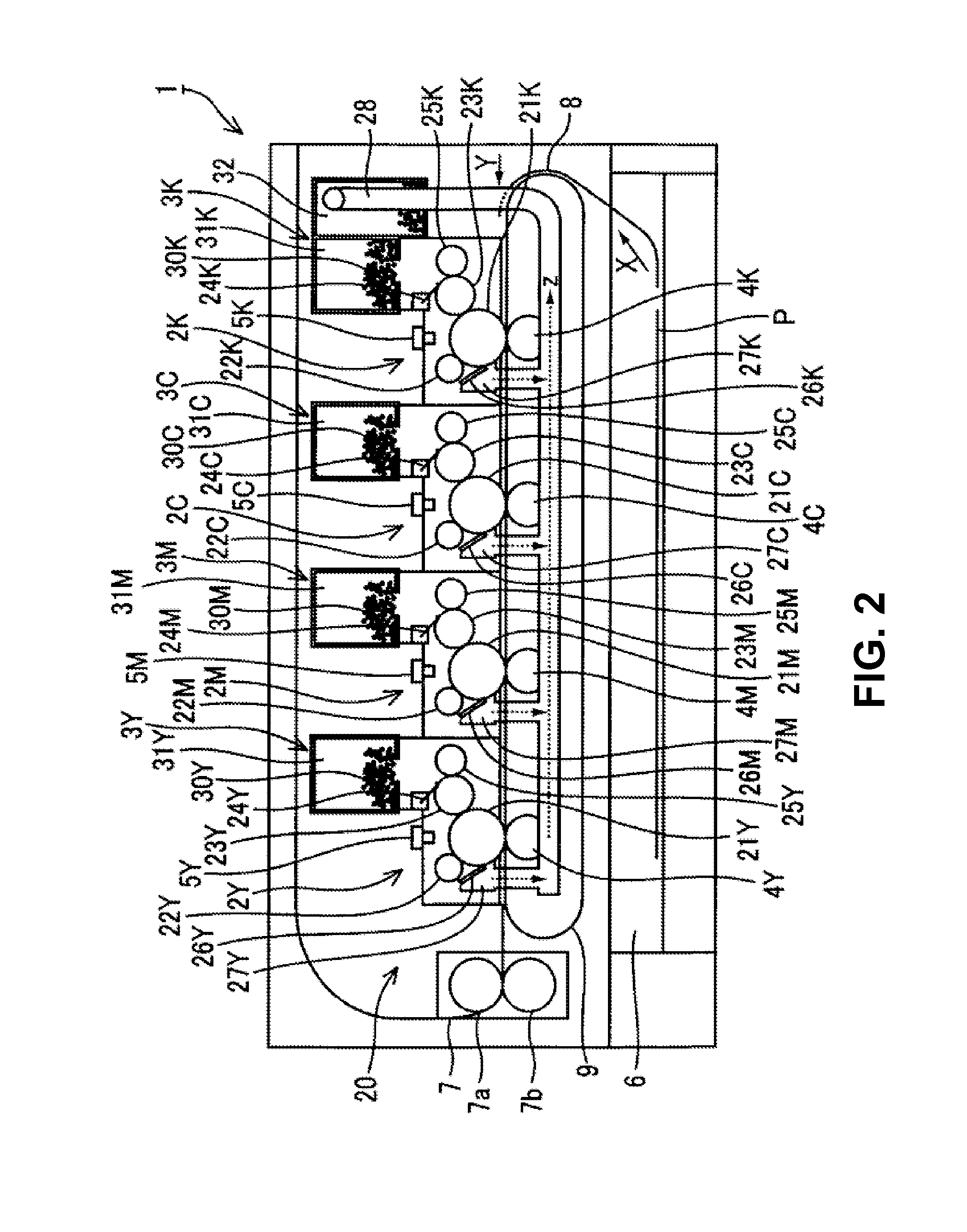
[0025]A first embodiment of the present invention will be explained. FIG. 2 is a schematic sectional view showing a configuration of a printer 1 as an image forming apparatus according to the first embodiment of the present invention.
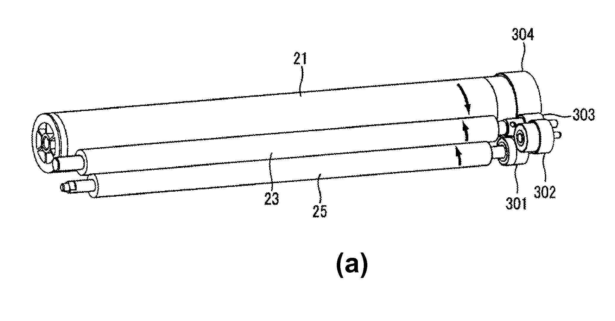
[0026]As shown in FIG. 2, the printer 1 includes developing devices 2 (2K, 2C, 2M, and 2Y) corresponding to toner 30 (30K, 30C, 30M, and 30Y) as developer in four colors of black (B), cyan (C), magenta (M), and yellow (Y); toner cartridges 3 (3K, 3C, 3M, and 3Y) for retaining the toner 30 (30K, 30C, 30M, and 30Y); and transfer units 4 (4K, 4C, 4M, and 4Y) for transferring toner images developed on photosensitive drums 21 (21K, 21C, 21M, and 21Y; described later) as static latent image supporting member to a sheet P as a transfer medium.
[0027]In the first embodiment, the printer 1 further includes exposure units 5 (5K, 5C, 5M, and 5Y) for irradiating surfaces of the photosensitive drums 21 to form the static latent images thereon; a sheet supply cassette...
second embodiment
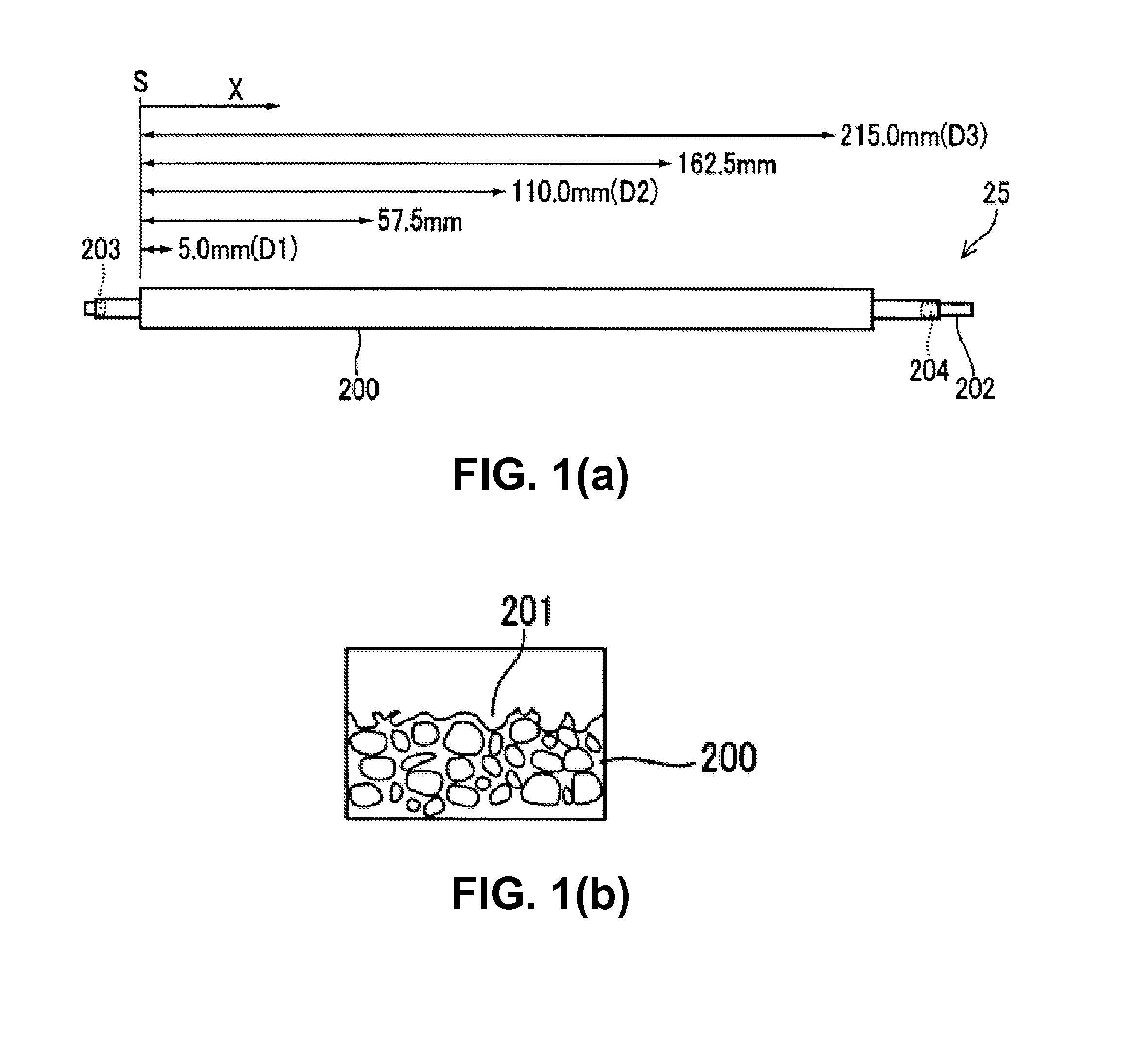
[0098]A second embodiment of the present invention will be explained next. In the second embodiment, the printer 1 as the image forming apparatus includes a supplying roller 25b having a shape different from that of the supplying roller 25 in the first embodiment. In the second embodiment, the printer 1 as the image forming apparatus, the image forming unit 20, and the exposure unit 5 have configurations similar to those in the first embodiment except the supplying roller 25. Accordingly, a similar component is designated with the same reference numeral, and an explanation thereof is omitted.
[0099]FIG. 8 is a schematic side view showing the supplying roller 25b of the printer 1 as the image forming apparatus according to the second embodiment of the present invention.
[0100]As shown in FIG. 8, the supplying roller 25b has an outer diameter φD1 at the point D1 is substantially the same as an outer diameter φD2 at the point D2, and an outer diameter φD3 at the point D3 is the smallest....
third embodiment
[0116]A third embodiment of the present invention will be explained next. In the third embodiment, the printer 1 as the image forming apparatus includes a supplying roller 25c having a shape different from that of the supplying roller 25 in the first embodiment and that of the supplying roller 25b in the second embodiment. In the third embodiment, the printer 1 as the image forming apparatus, the image forming unit 20, and the exposure unit 5 have configurations similar to those in the first embodiment except the supplying roller 25 and those in the second embodiment except the supplying roller 25b. Accordingly, a similar component is designated with the same reference numeral, and an explanation thereof is omitted.
[0117]FIG. 10 is a schematic side view showing the supplying roller 25c of the printer 1 as the image forming apparatus according to the third embodiment of the present invention.
[0118]As shown in FIG. 10, the supplying roller 25c has a largest outer diameter φD2 at the p...
PUM
 Abstract
Description
Claims
Application Information
 - R&D
- Intellectual Property
- Life Sciences
- Materials
- Tech Scout
- Unparalleled Data Quality
- Higher Quality Content
- 60% Fewer Hallucinations
Browse by: Latest US Patents, China's latest patents, Technical Efficacy Thesaurus, Application Domain, Technology Topic, Popular Technical Reports.
© 2025 PatSnap. All rights reserved.Legal|Privacy policy|Modern Slavery Act Transparency Statement|Sitemap|About US| Contact US: help@patsnap.com


