
System and method for inspecting a route during movement of a vehicle system over the route

a vehicle system and inspection system technology, applied in the field of inspection systems, can solve the problems of inconvenient inspection, inability to inspect for a variety of other types of damage to the track, and relatively slow system, etc., and achieve the effect of increasing the cost and maintenance of the fleet without contributing to the capacity of the fl

Inactive Publication Date: 2013-11-28
GENERAL ELECTRIC CO
View PDF1 Cites 95 Cited by
  • Summary
  • Abstract
  • Description
  • Claims
  • Application Information

AI Technical Summary

Benefits of technology

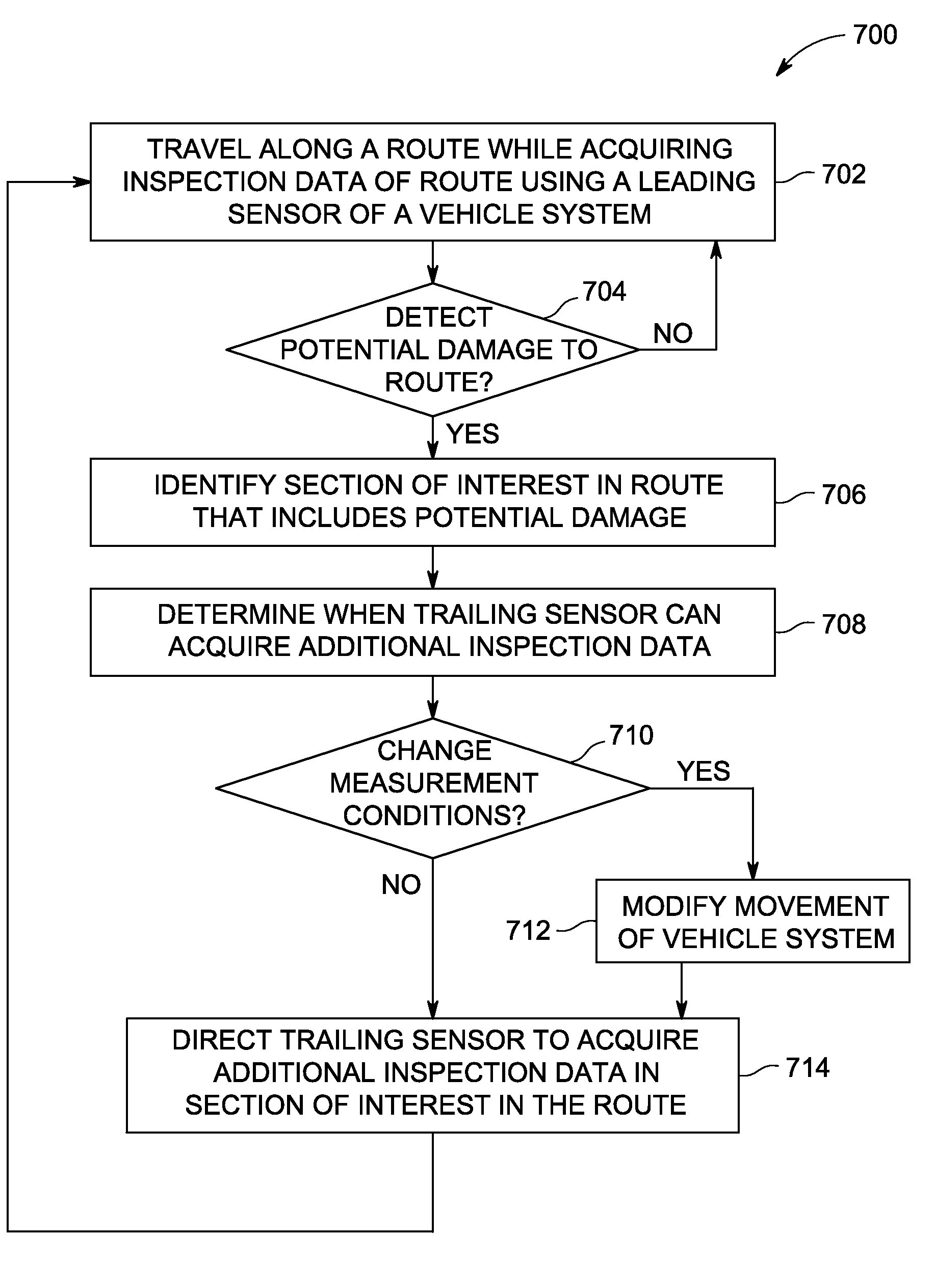
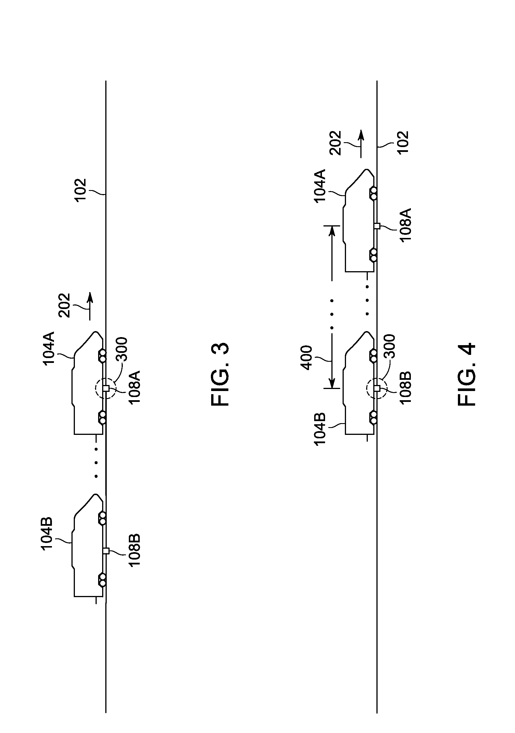
The patent describes a sensing system that includes a leading sensor and a trailing sensor to inspect a route as a vehicle system travels over it. The leading sensor acquires first inspection data, while the trailing sensor acquires second inspection data. The route examining unit identifies damage in the route and directs the trailing sensor to acquire second inspection data in the damaged section of the route. This system helps to quickly identify and locate damage to the route, allowing for timely repairs or replacement.

Problems solved by technology

Such systems are relatively slow and are not useful for inspecting the route over relatively long distances.
But, these systems are fixed in location and may be unable to inspect for a variety of other types of damage to the track other than broken rails.
Consequently, these types of vehicles add to the cost and maintenance of a fleet of vehicles without contributing to the capacity of the fleet to convey cargo or passengers.
Others of these types of vehicle mounted systems may be limited by using only a single type of sensor.
Still others of these vehicle mounted inspection systems are limited in the types of sensors that can be used due to the relatively fast travel of the vehicles.
The specially designed vehicles can be relatively expensive and add to the cost and maintenance of a fleet of vehicles.

Method used


Image

  • System and method for inspecting a route during movement of a vehicle system over the route
  • System and method for inspecting a route during movement of a vehicle system over the route
  • System and method for inspecting a route during movement of a vehicle system over the route

Examples


Embodiment Construction

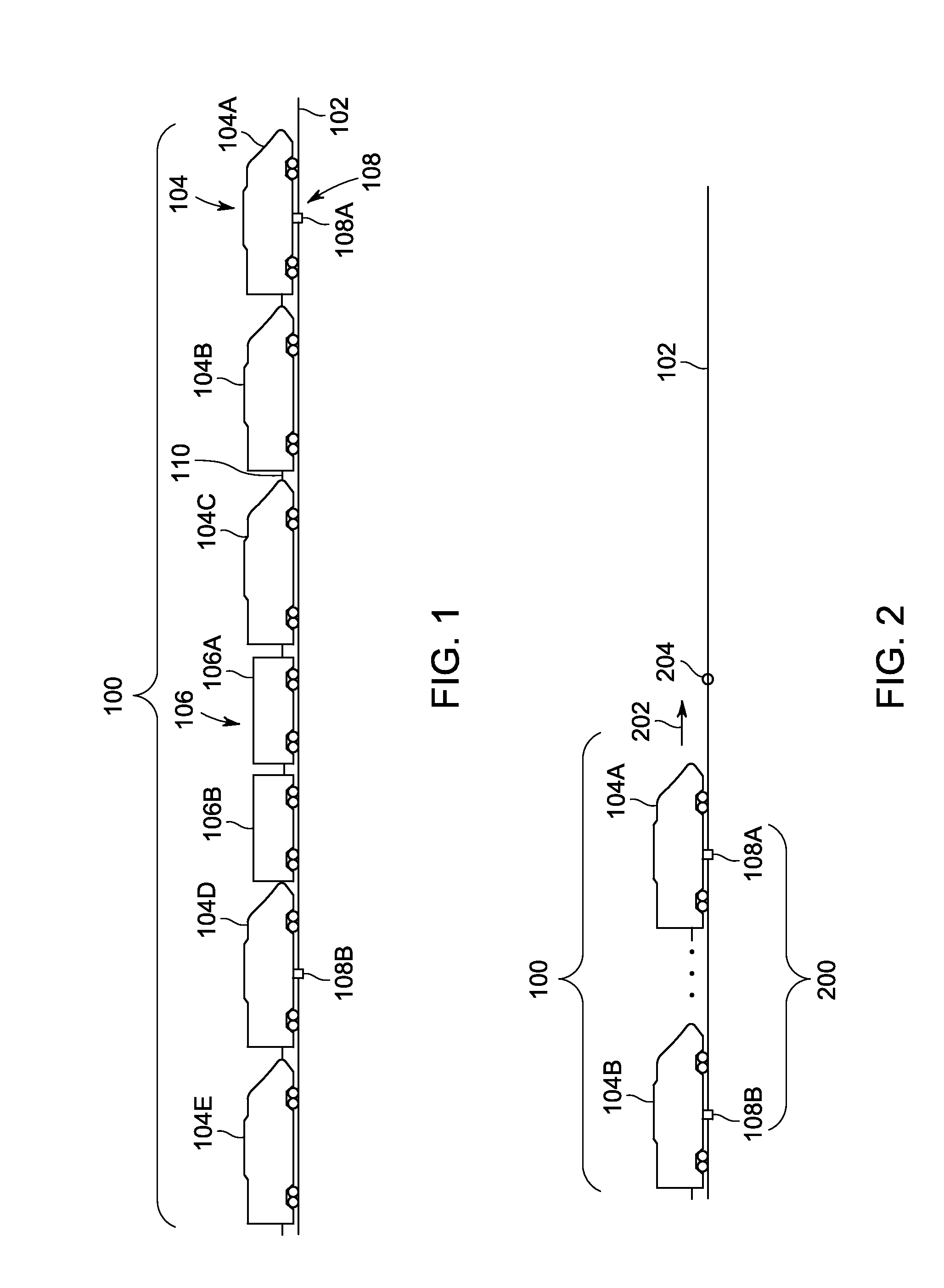
[0020]FIG. 1 is a schematic diagram of a vehicle system 100 traveling along a route 102 in accordance with one embodiment of the inventive subject matter. The vehicle system 100 includes several powered vehicles 104 (e.g., powered vehicles 104A-E) and several non-powered vehicles 106 (e.g., non-powered vehicles 106A-B) mechanically interconnected with each other such that the vehicles 104, 106 travel together as a unit. The vehicles 104, 106 may be connected with each other by coupler devices 110. The terms “powered” and “non-powered” indicate the capability of the different vehicles 104, 106 to self-propel. For example, the powered vehicles 104 represent vehicles that are capable of self-propulsion (e.g., that include motors that generate tractive effort). The non-powered vehicles 106 represent vehicles that are incapable of self-propulsion (e.g., do not include motors that generate tractive effort), but may otherwise receive or use electric current for one or more purposes other t...


PUM


Abstract

A sensing system includes a leading sensor, a trailing sensor, and a route examining unit. The sensors are coupled to a vehicle system that travels along a route. The leading sensor acquires first inspection data indicative of a condition of the route as the vehicle system travels over the route. The condition may represent the health of the route. The trailing sensor acquires additional, second inspection data that is indicative of the condition to the route subsequent to the leading sensor acquiring the first inspection data. The route examining unit identifies a section of interest in the route based on the first inspection data acquired by the leading sensor. The route examining unit also directs the trailing sensor to acquire the second inspection data within the section of interest in the route when the first inspection data indicates damage to the route in the section of interest.

Description

FIELD[0001]The inventive subject matter described herein relates to inspection systemsBACKGROUND[0002]Known inspection systems are used to examine routes traveled by vehicles for damage. For example, a variety of handheld, trackside, and vehicle mounted systems are used to examine railroad tracks for damage, such as cracks, pitting, or breaks. These systems are used to identify damage to the tracks prior to the damage becoming severe enough to cause accidents by vehicles on the tracks. Once the systems identify the damage, maintenance can be scheduled to repair or replace the damaged portion of the tracks.[0003]Some known handheld inspection systems are carried by a human operator as the operator walks alongside the route. Such systems are relatively slow and are not useful for inspecting the route over relatively long distances. Some known trackside inspection systems use electronic currents transmitted through the rails of a track to inspect for broken rails. But, these systems ar...

Claims


Application Information

Patent Timeline
Patent Type & Authority Applications(United States)
IPC IPC(8): G06F19/00G06F17/00
CPCB61L3/121B61L15/0036B61L23/044B61L25/025B61L2205/04G01N29/265G01N2291/101G01N2291/2632
Inventor COOPER, JARED KLINEMANKRAELING, MARK BRADSHAWSMITH, EUGENE A.CORRY, JAMES GLENMCKAY, DAVID LOWELLMCMANUS, BRIAN JOSEPHSZEWCZYK, KEITH
Owner GENERAL ELECTRIC CO
Learn More