
Wheel bearing for a utility vehicle

a technology for utility vehicles and bearings, applied in bearings, roller bearings, shafts, etc., can solve the problems of increased fuel consumption, higher loss of lubricant, and more soiling on roller bearings, and achieve the effect of improving the bearing

Inactive Publication Date: 2013-11-28
SCHAEFFLER TECH AG & CO KG
View PDF7 Cites 11 Cited by
  • Summary
  • Abstract
  • Description
  • Claims
  • Application Information

AI Technical Summary

Benefits of technology

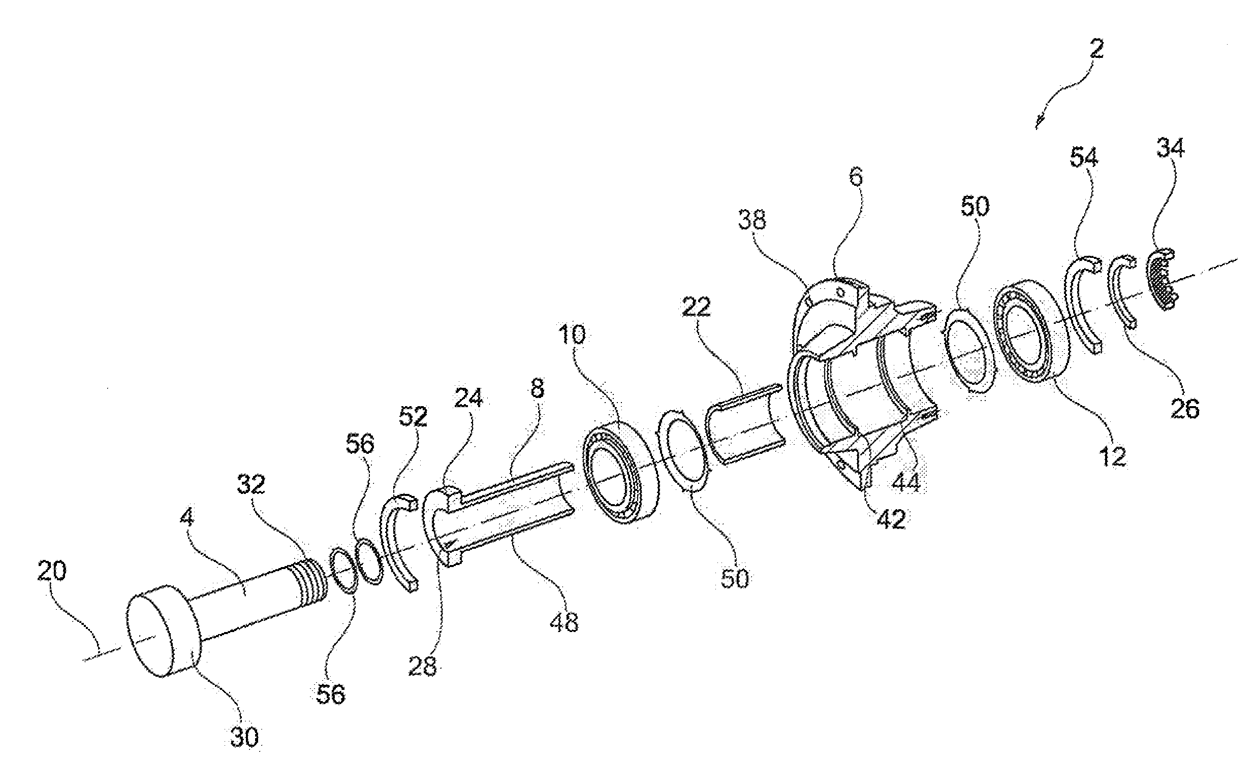
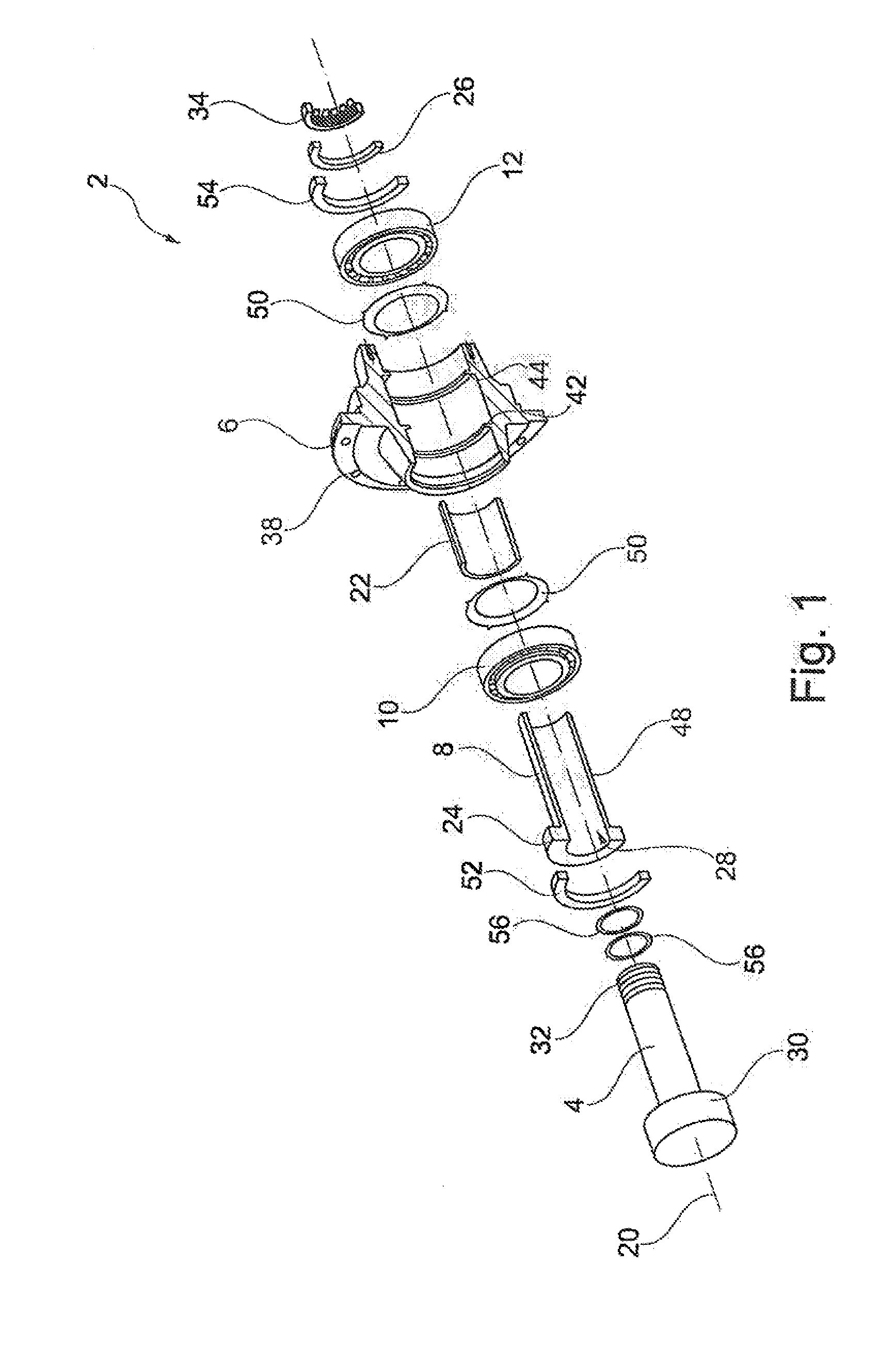
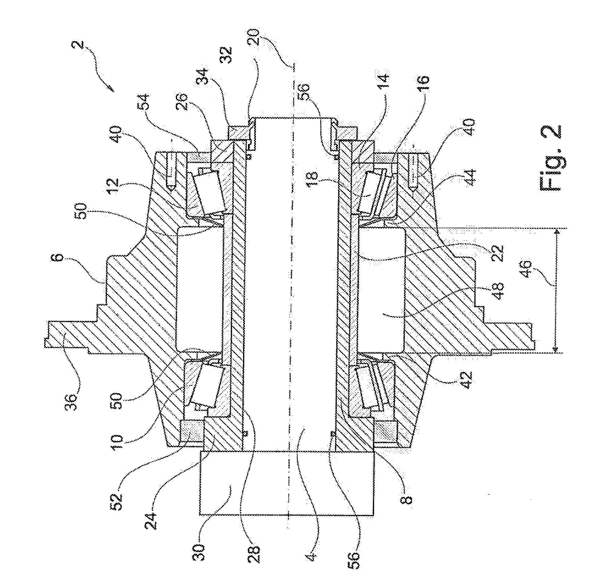
[0010]Owing to the carrier shaft and the roller bearings, which are axially clamped on the carrier shaft, all of the elements of a wheel bearing can be prefabricated at a low cost and can be installed in the utility vehicle. In contrast to the wheel bearing designed as a unit, the individual elements of the proposed wheel bearing can be exchanged, for example, for maintenance purposes, when the proposed wheel bearing fails, for example, due to overload phenomena. This exchange does not have to be performed on the utility vehicle itself, but rather can be done after the entire wheel bearing has been removed in an environment that is provided for this purpose, such as on a work bench. If the proposed wheel bearing is exchanged for a new wheel bearing, at least those components of the damaged wheel bearing that are still functional can be re-used. Therefore, the proposed wheel bearing can not only lower the maintenance costs of a wheel bearing, but also its design as a functional unit allows the proposed wheel bearing to be installed with little technical effort, even though the individual components of the wheel bearing can be exchanged at a later date (like the roller bearing) or can be replaced (like the lubricant).
[0015]Although the first roller bearing can be secured on the carrier shaft in such a way that an inner ring of the roller bearing cannot be rotated relative to the carrier shaft, the proposed wheel bearing includes, in another embodiment, an additional axial end stop for axially abutting the first roller bearing on the carrier shaft. This axial end stop makes it easy to push the two roller bearings onto the carrier shaft and to clamp them together by means of a cold formed collar.
[0016]In yet another embodiment, the proposed wheel bearing includes a spacer sleeve that is fitted concentrically on the carrier shaft and that is disposed axially between an inner ring of the first roller bearing and an inner ring of the second roller bearing and that transfers at least some of the tensioning force from the second roller bearing to the first roller bearing. The spacer sleeve makes it possible to clamp the inner rings of the two roller bearings firmly together in the axial direction and, in so doing, to secure them to the carrier shaft of the proposed wheel bearing. The pre-stress of the two roller bearings can be not only defined with exact precision by means of the spacer sleeve, but also preserved on a permanent basis, because a major portion of the axial force, holding the roller bearings on the carrier sleeve, can be absorbed by the spacer sleeve. In this case the outer rings of the roller bearings make axial contact and, in so doing, enable a pre-stress only to the extent it is allowed by the axial expansion of the spacer sleeve.
[0017]In another embodiment, the wheel hub of the proposed wheel bearing has a radially inwards pointing projection that engages axially between an outer ring of the first roller bearing and an outer ring of the second roller bearing. The axial expansion of this projection enables a precision adjustment of the pre-stress in the two roller bearings.

Problems solved by technology

In addition, the roller bearings are subject to more soiling and a higher rate of wear, disadvantages that become apparent, for example, due to an increase in the fuel consumption.
In addition, it is often the case that under normal operating conditions there is a higher loss of lubricant, a feature that is associated with a maintenance and service requirement for re-greasing the roller bearings.
Finally such wheel bearings do not allow the pre-stress to be adjusted for purposes of reducing the axial play and holding the pre-stress at a specified value over a longer service life.
However, the manufacture of such wheel bearings can be as much as 150% more expensive than the manufacture of the first mentioned wheel bearing variants.

Method used


Image

  • Wheel bearing for a utility vehicle
  • Wheel bearing for a utility vehicle
  • Wheel bearing for a utility vehicle

Examples


Embodiment Construction

[0036]At the outset, it should be appreciated that like drawing numbers on different drawing views identify identical, or functionally similar, structural elements of the invention. While the present invention is described with respect to what is presently considered to be the preferred aspects, it is to be understood that the invention as claimed is not limited to the disclosed aspects.

[0037]Furthermore, it is understood that this invention is not limited to the particular methodology, materials and modifications described and, as such, may, of course, vary. It is also understood that the terminology used herein is for the purpose of describing particular aspects only, and is not intended to limit the scope of the present invention, which is limited only by the appended claims.

[0038]Unless defined otherwise, all technical and scientific terms used herein have the same meaning as commonly understood to one of ordinary skill in the art to which this invention belongs. Although any me...


PUM

PropertyMeasurementUnit
tensioning forceaaaaaaaaaa
forcesaaaaaaaaaa
pre-stressaaaaaaaaaa

Abstract

The invention relates to wheel bearing that is intended for a utility vehicle and includes a sleeve-shaped carrier shaft, in which an axle of the utility vehicle can be received in a concentric manner; a wheel hub; and a first roller bearing and a second roller bearing for rolling the wheel hub relative to the carrier shaft. In this case the second roller bearing is clamped axially against the first roller bearing on the sleeve-shaped carrier shaft by means of a press ring.

Description

CROSS-REFERENCE TO RELATED APPLICATIONS[0001]This patent claims priority from German Patent Application No. DE 10 2011 076 275.2, filed May 23, 2011, which application is incorporated herein by reference in its entirety.FIELD OF THE INVENTION[0002]The invention relates to a wheel bearing for a utility vehicle, the utility vehicle, and a method for manufacturing a wheel bearing for a utility vehicle.BACKGROUND OF THE INVENTION[0003]Wheel bearings are mounted in the center of a wheel and are used in vehicles to attach the wheel to the vehicle frame in such a way that the wheel can be rotated. The wheel bearing separates the rotatable components on the vehicle, like the wheel hub, from the stationary components on the vehicle, like the wheel suspension. The wheel bearing guides the forces and the moments from the road to the vehicle body and vice versa.BRIEF SUMMARY OF THE INVENTION[0004]One object of the present invention is to provide an improved wheel bearing for a vehicle.[0005]The...

Claims


Application Information

Patent Timeline
Patent Type & Authority Applications(United States)
IPC IPC(8): F16C19/24B23P17/00B60B27/02
CPCB60B27/001B60B27/0084F16C19/364F16C19/548F16C35/073F16C2226/52F16C2326/02Y10T29/49679Y10T29/49682
Inventor RUEDI, CARLOSCAMILO, ALEXANDREDE MATOS, OSMARGRACIANO, MARCO AURELIO
Owner SCHAEFFLER TECH AG & CO KG
Learn More