Solar cell module
a solar cell and module technology, applied in the direction of heat collector mounting/support, pv power plants, light and heating apparatus, etc., can solve the problems of large wind load and large snow load, and thus be more likely to be damaged, so as to reduce shearing stress and reduce the effect of shearing stress and simple structur
- Summary
- Abstract
- Description
- Claims
- Application Information
AI Technical Summary
Benefits of technology
Problems solved by technology
Method used
Image
Examples
first embodiment
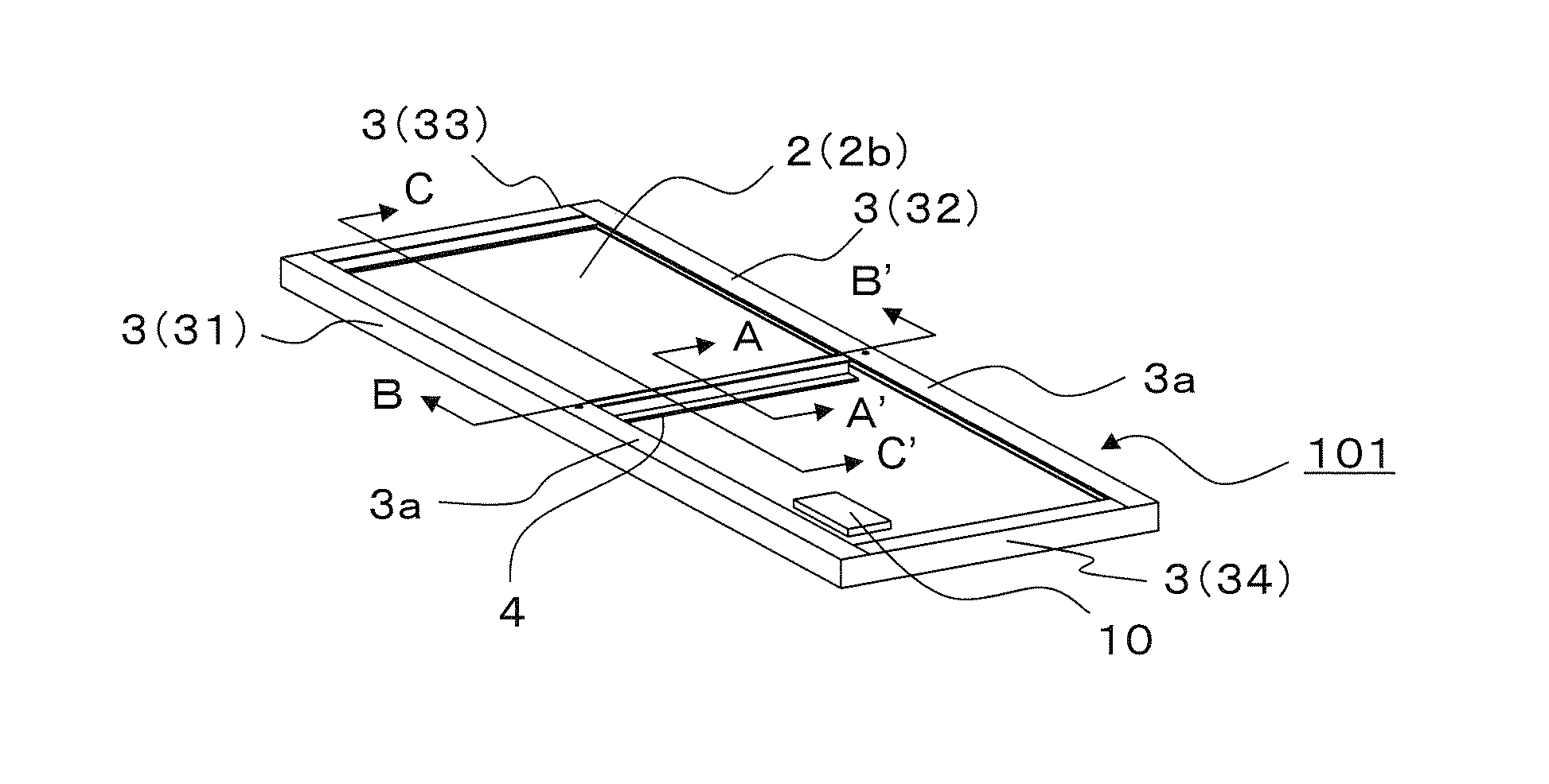
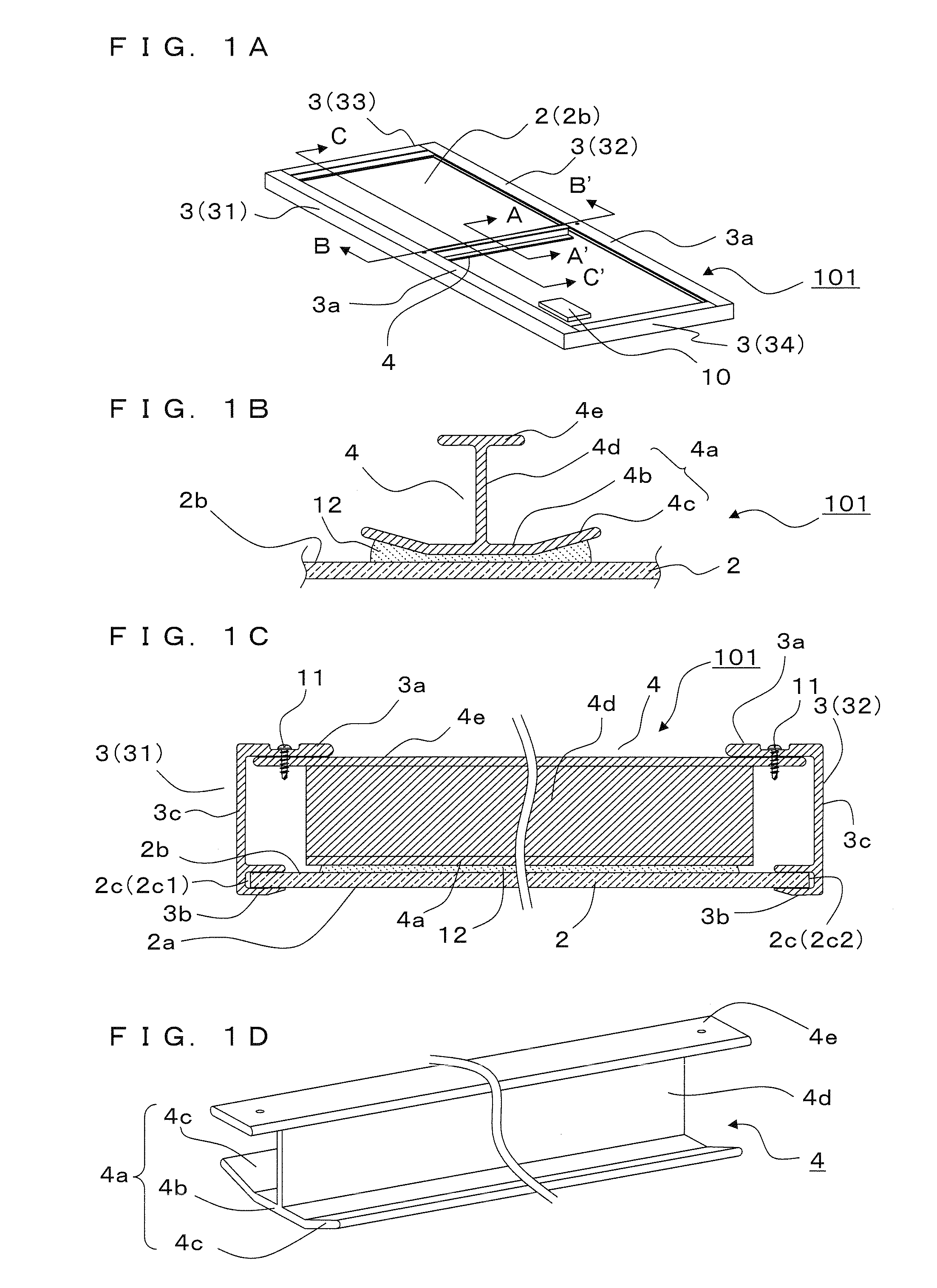
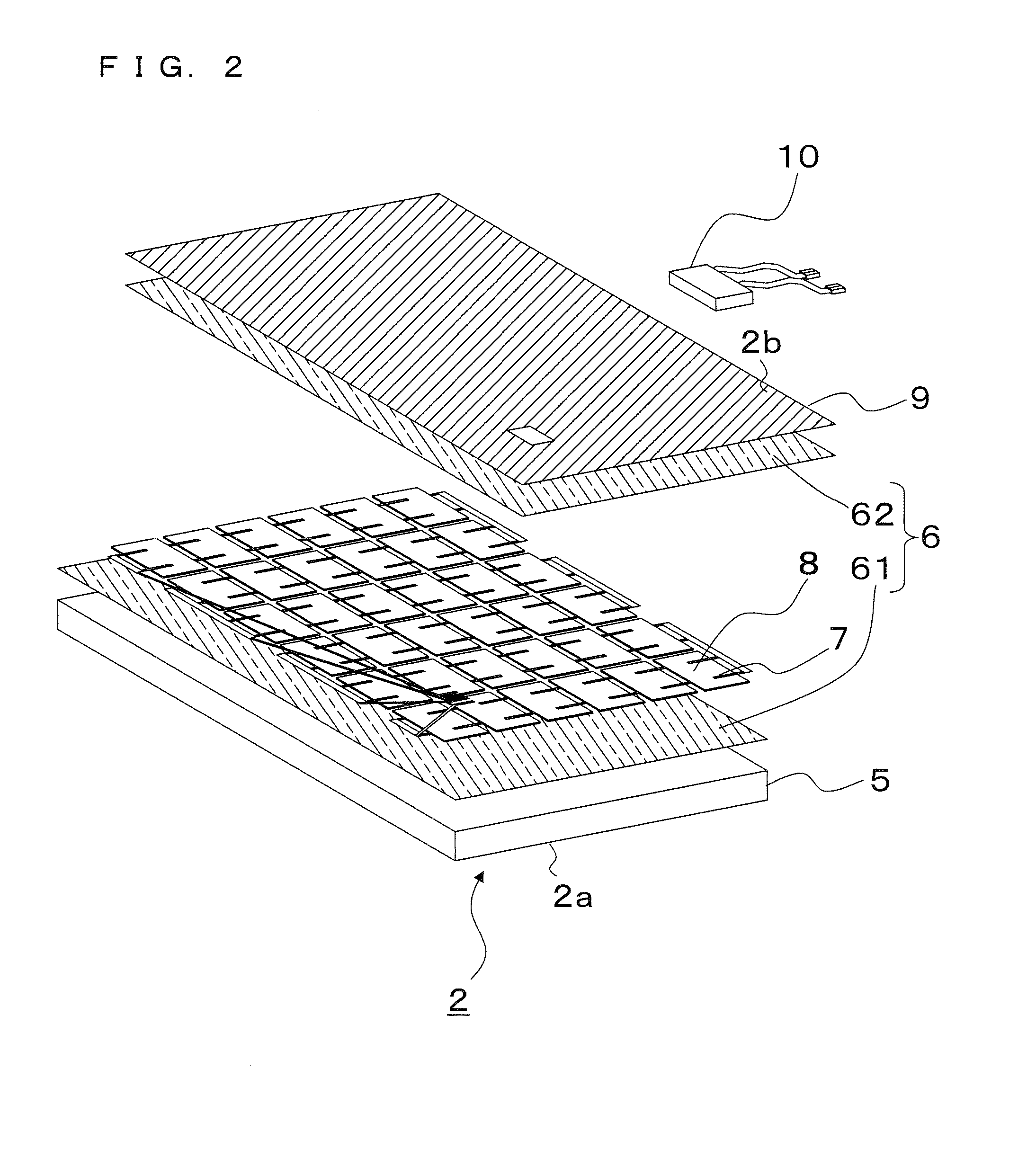
[0024]A solar cell module 101 according to a first embodiment will be described with reference to FIGS. 1A to 3.
[0025]Basically, as illustrated in FIGS. 1A and 1C, the solar cell module 101 includes, for example, a solar cell panel 2, which is rectangular in a plan view, a retaining member 3 that retains the outer edges of the solar cell panel 2, and a reinforcing member 4. The retaining member 3 includes, for example, a first retaining part 31 and a second retaining part 32 that retain a pair of side parts 2c (first side part 2c1 and second side part 2c2), which are mutually substantially parallel, of the solar cell panel 2, a third retaining part 33 and a fourth retaining member 34 that retain another pair of side parts, which are mutually substantially parallel, of the solar cell panel 2. The solar cell module 101 may further includes a terminal box 10, which is used to supply an output from the solar cell panel 2, on a non-light-receiving surface 2b equivalent to the rear surfac...
second embodiment
[0054]Next, a solar cell module 102 according to a second embodiment of the present invention will be described with reference to FIG. 5.
[0055]In the solar cell module 102 according to this embodiment, the reinforcing member 4 has a different shape than in the solar cell module 101 according to the first embodiment. Specifically, as illustrated in FIG. 5, the reinforcing member 4 further includes a linking part 4f that links the horizontal part 4b and inclined part 4c together. The thickness of the linking part 4f is smaller than the thickness of the horizontal part 4b and is also smaller than the thickness of the inclined part 4c. That is, the solar cell module 102 differs from the first embodiment in that the reinforcing member 4 is likely to be warped by being thinned at a linking part between the horizontal part 4b and the inclined part 4c.
[0056]In this structure, for example, the linking part between the horizontal part 4b and the inclined part 4c may be cut on the same side a...
third embodiment
[0060]Next, a solar cell module 103 according to a third embodiment of the present invention will be described with reference to FIG. 6. The solar cell module 103 according to this embodiment differs from the first embodiment in the shape of the reinforcing member 4.
[0061]Specifically, as illustrated in FIG. 6, a thickness of the inclined part 4c is smaller than a thickness of the horizontal part 4b in the solar cell module 103 according to this embodiment. In this structure as well, it can be said that, as in the second embodiment, the linking portion between the horizontal part 4b and the inclined part 4c is thinned. That is, this embodiment has a shape in which the thickness of the support part 4a is reduced ahead of the linking part between the horizontal part 4b and the inclined part 4c.
[0062]In this structure as well, a warp is likely to occur at the linking part between the horizontal part 4b and inclined part 4c of the reinforcing member 4 as in the second embodiment. Thus,...
PUM
 Abstract
Description
Claims
Application Information
 - R&D
- Intellectual Property
- Life Sciences
- Materials
- Tech Scout
- Unparalleled Data Quality
- Higher Quality Content
- 60% Fewer Hallucinations
Browse by: Latest US Patents, China's latest patents, Technical Efficacy Thesaurus, Application Domain, Technology Topic, Popular Technical Reports.
© 2025 PatSnap. All rights reserved.Legal|Privacy policy|Modern Slavery Act Transparency Statement|Sitemap|About US| Contact US: help@patsnap.com


