Electrically Assisted Cycle Kit

a technology of electric assisted cycle and kit, which is applied in the field of pedal cycles, can solve the problems of not being able to determine the direction of rotation of proximity sensors, difficult fitting, and difficult to meet every eventuality, and achieve the effects of improving the grip of the sensor attachment on the frame, improving the grip, and improving the grip

Active Publication Date: 2013-11-21
MODERN TIMES
View PDF21 Cites 14 Cited by
  • Summary
  • Abstract
  • Description
  • Claims
  • Application Information

AI Technical Summary

Benefits of technology

[0037]The sensor attachment may have a plurality of pivotable gripping members having a gripping surface for gripping the frame of the cycle. Since the gripping members pivot, they can grip round frames of different shapes and sizes, making it easier to fit the gear tooth sensor to any type of cycle. Also, since there are multiple gripping members, the sensor attachment can contact the frame at multiple points, improving the grip of the sensor attachment on the frame.
[0038]The gripping members may have a concave gripping surface. This is useful because a concave surface can contact the frame at multiple points along the curved surface, increasing the grip achieved by the sensor attachment in comparison to a straight or convex surface. It will be appreciated that the concave surface does not necessarily need to form a regular curve (although in some embodiments it may do)—it may simply provide a generally hollowed internal region which extends inwards between the edges of the surface.
[0039]At least the gripping surface of the gripping members may be made from a slip-resistant material, such as rubber. For example, a thin adhesive foam rubber sheet may be applied to the gripping surface of the gripping members to provide some adhesion to the frame of the cycle. By providing a slip-resistant material which makes the gripping surface slightly tacky or frictioned, the sensor attachment can be held firmly in place without slippage.
[0040]The gripping members may also have a non-gripping surface which has a groove for accommodating a securing strap. This enables a flexible strap such as a cable tie or wire to bind the gripping members to the frame, with the groove preventing the strap slipping laterally off the gripping members. A further groove may be provided in the support platform base unit to li...

Problems solved by technology

The key disadvantage of such sensors is that they require a manufactured target device to be made in each case and fixed accurately and robustly to the pedal cycle for it to work.
Given the very wide range of pedal cycle configurations possible, satisfying every eventuality is very difficult and fitting is not easy.
While proximity sensors using a single magnetic target may be easier to fit than the other kinds of sensors and targets, the proxim...

Method used


Image

  • Electrically Assisted Cycle Kit
  • Electrically Assisted Cycle Kit
  • Electrically Assisted Cycle Kit

Examples


Embodiment Construction

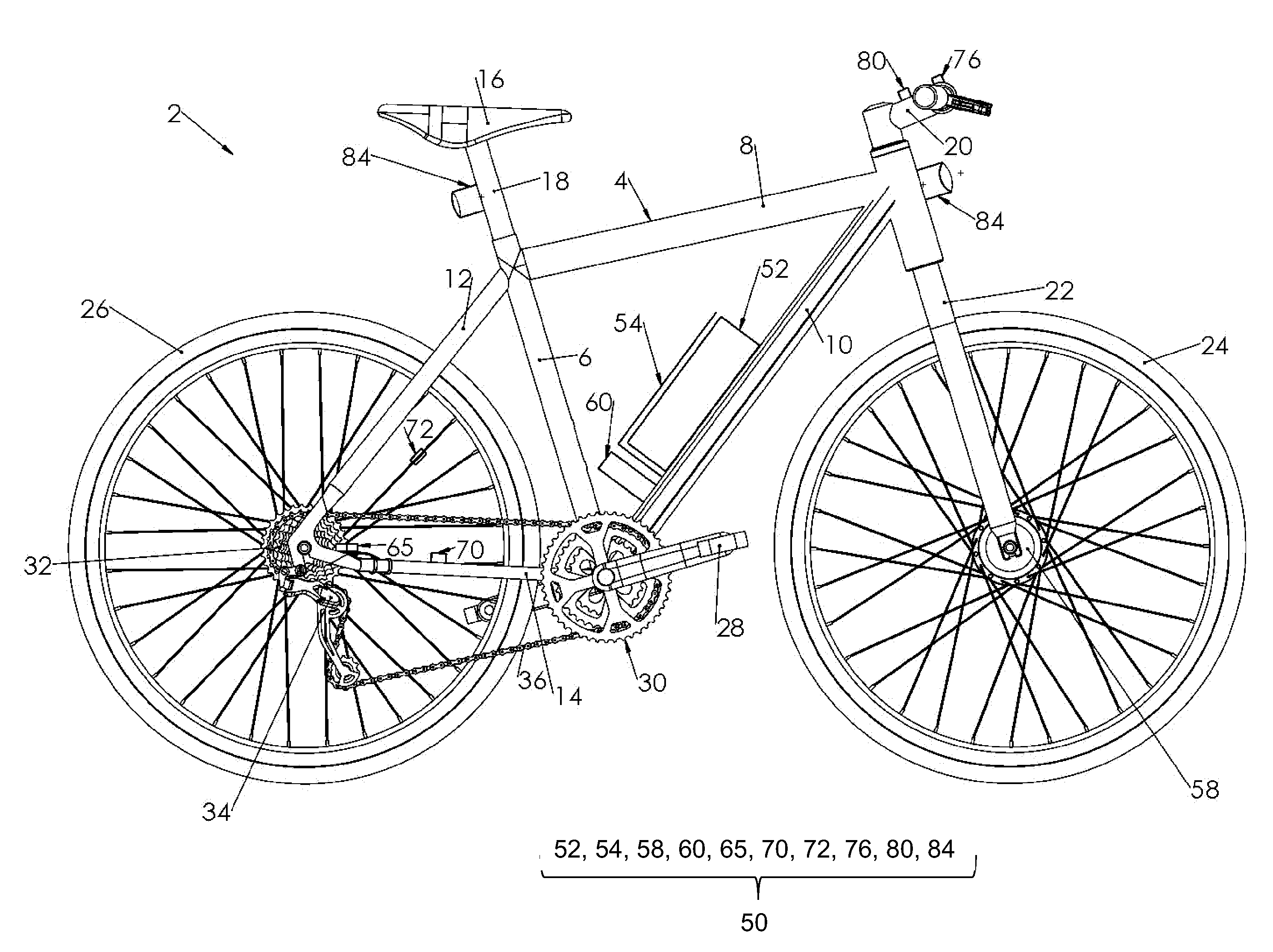
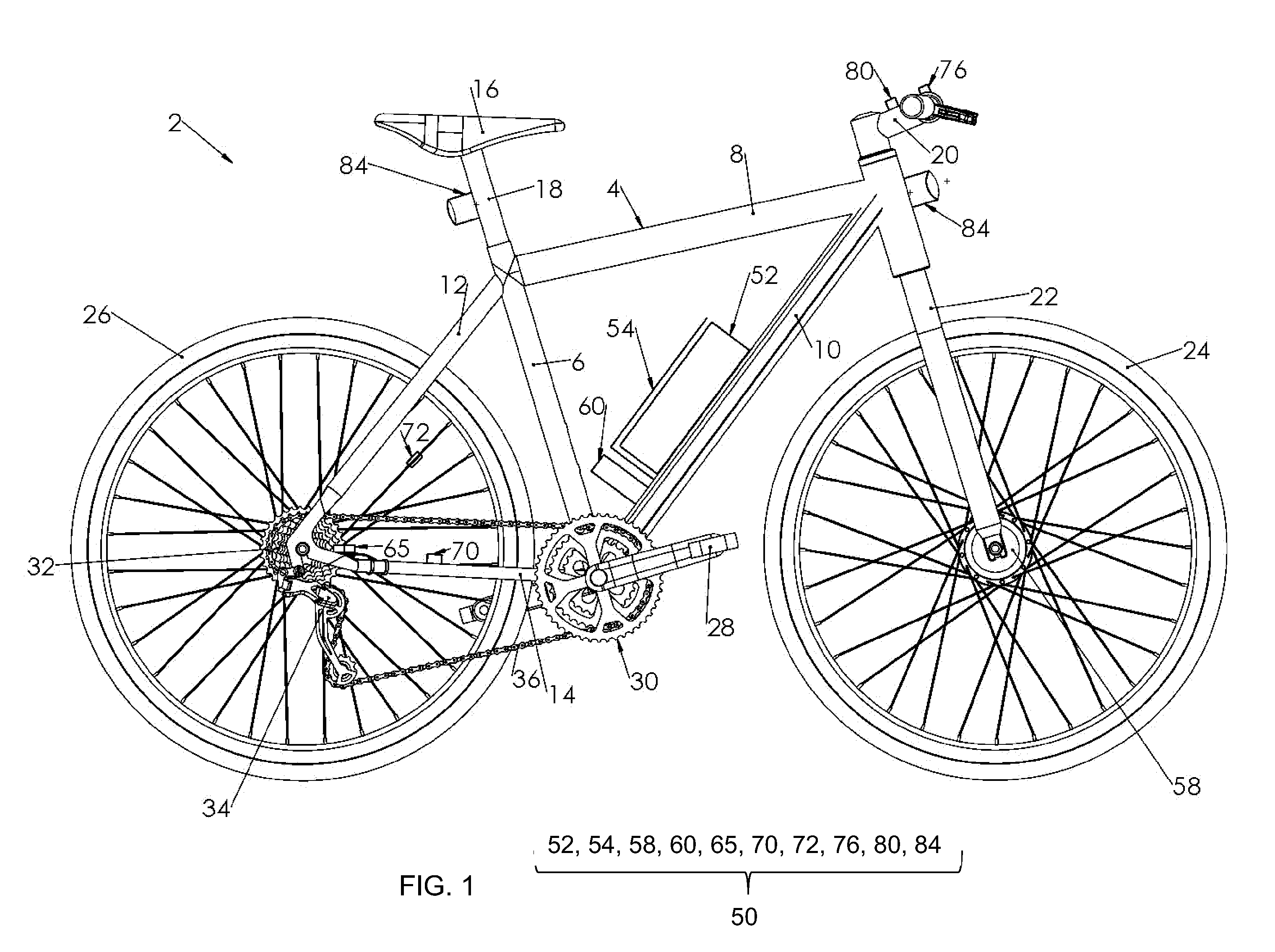
[0072]FIG. 1 schematically illustrates a pedal cycle 2. While FIG. 1 shows a typical pedal bicycle, it will be appreciated that the present technique could also be applied to other types of cycles such as a tricycle or a tandem. The pedal cycle 2 may be an existing cycle for which no electrical assistance is originally provided. The pedal cycle 2 comprises a frame 4 including a seat tube 6, top tube 8, down tube 10, seat stays 12, and chain stays 14. The cycle 2 also includes a saddle 16, seat post 18, handle bars 20, front fork 22, front wheel 24, rear wheel 26, pedals 28, front sprockets or chain rings 30, rear sprockets 32, derailleur 34 and chain 36.

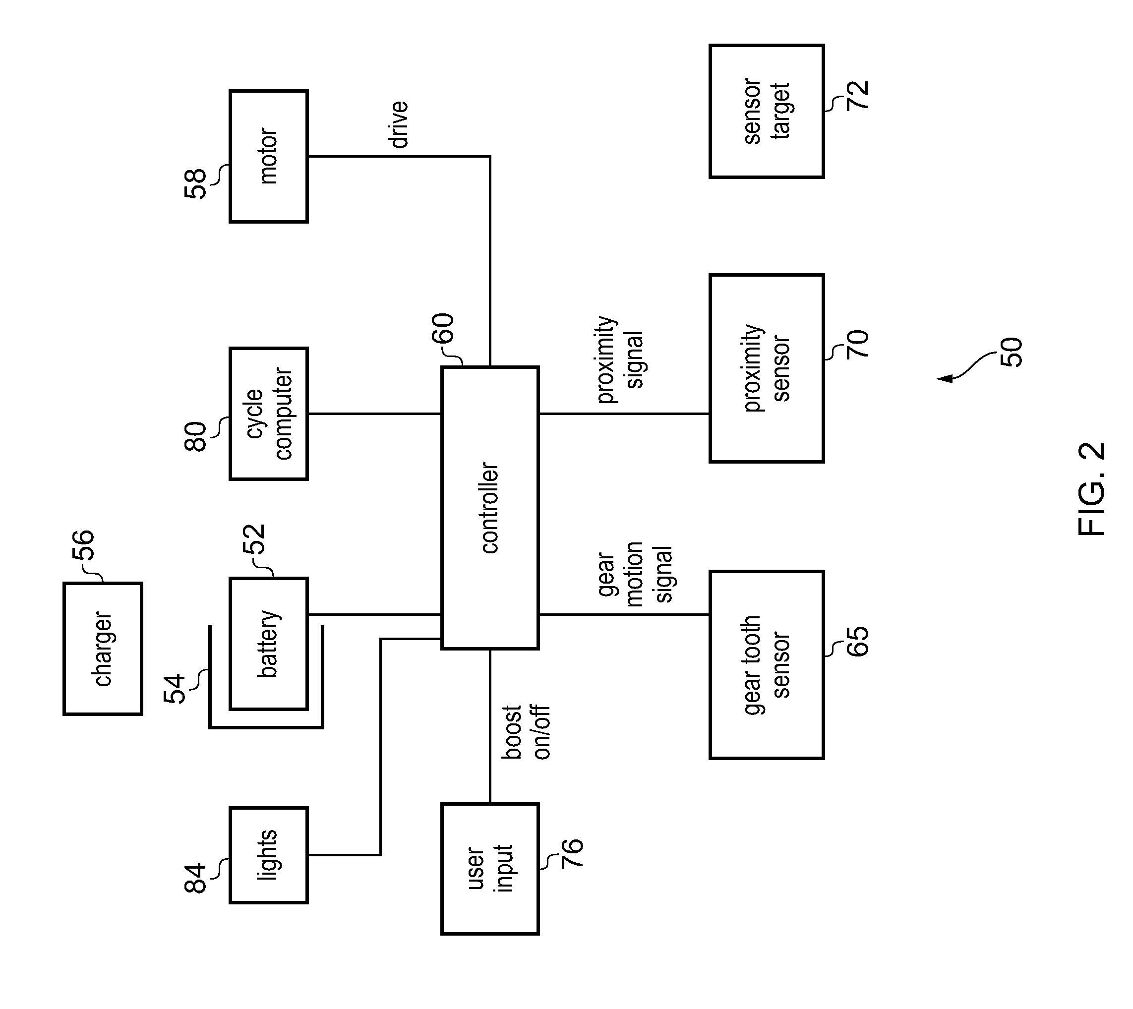
[0073]To provide assistance with pedal cycle motion, the cycle 2 is fitted with an electrically assisted cycle kit 50. The kit 50 is shown functionally in FIG. 2 and shown fitted to the cycle 2 in FIG. 1. By fitting the components of the cycle kit 50 to the cycle 2, a standard cycle 2 can be converted into an electrically assisted cy...


PUM

PropertyMeasurementUnit
Electrical resistanceaaaaaaaaaa
Speedaaaaaaaaaa
Displacementaaaaaaaaaa

Abstract

An electrically assisted cycle kit 50 for fitting to a pedal cycle 2 comprises an electric motor 58 for assisting pedal cycle motion, a battery 52 for powering the motor 58, and a controller 60 for controlling the drive of the motor 58. A gear tooth sensor 65 provides a gear motion signal indicative of the speed/acceleration of motion of gear teeth 94 and valleys 95 of a gear sprocket 32 of the cycle. The controller controls the drive of the motor 58 in dependence on the gear motion signal.

Description

BACKGROUND OF THE INVENTIONField of the Invention[0001]The present invention relates to the field of pedal cycles. More particularly, the invention relates to an electrically assisted cycle kit for fitting to a pedal cycle, a pedal cycle fitted with the kit, a method of fitting the kit to the pedal cycle, and an attachment for attaching an object to a pedal cycle.INTRODUCTION[0002]Electrically assisted pedal cycles include an electric motor for assisting with pedal cycle motion of the cyclist. The drive of the motor is typically controlled based on the pedalling speed of the cyclist, so that the motor provides assistance when the cyclist is pedalling but does not drive when the cyclist brakes or stops pedalling. To enable safe regulation of the drive of the motor, the cycle is typically provided with sensors for sensing the speed at which the cyclist is pedalling. Various kinds of sensors may be used to sense the pedalling speed, including simple proximity switches which sense a mag...

Claims


Application Information

Patent Timeline
IPC IPC(8): B62M6/50F16M13/02
CPCB62M6/50F16M13/022Y10T29/49002B62J11/00
Inventor SEARLES, MARK AUBREY
Owner MODERN TIMES
Why Eureka
Try Eureka