
Illuminating optical system and projection display apparatus

a technology of illumination optical system and projection display apparatus, which is applied in the direction of lighting and heating apparatus, semiconductor devices for light sources, instruments, etc., can solve the problems of non-uniform light intensity of illuminating light beam output from rod integrator after passing therethrough, deterioration of quality of illuminating light beam, and inability to achieve uniform light intensity, the effect of suppressing generation of illumination fluctuations

Active Publication Date: 2013-11-21
FUJIFILM CORP
View PDF4 Cites 3 Cited by
  • Summary
  • Abstract
  • Description
  • Claims
  • Application Information

AI Technical Summary

Benefits of technology

The patent describes a system that adjusts the brightness and angle of light beams to improve the efficiency and reduce fluctuations in the output of light. This is achieved by using relays and a rod integrator to match the spreading angles and sizes of light beams from different sources. The system does not require a larger apparatus or additional components, resulting in improved performance and reduced costs.

Problems solved by technology

When a plurality of light beams output from at least one light source and another light source of a different type are caused to pass through a single rod integrator via relay lenses having magnification ratios of 1× to form an illuminating light beam, there are cases in which the quality of the illuminating light beam deteriorates.
Particularly, the quality of an illuminating light beam becomes more likely to deteriorate when light beams output from a plurality of light sources of different types are caused to pass through a single rod integrator via relay lenses having a magnification ratio of 1× to form the illuminating light beam.
Accordingly, the light intensity of an illuminating light beam output from the rod integrator after passing therethrough becomes non uniform, and fluctuations are generated in the light intensity distribution thereof.
Therefore, the number of times that the light beams are reflected within the interior of the rod integrator increases, and light propagation loss due to decreased reflectance, etc. increases.

Method used


Image

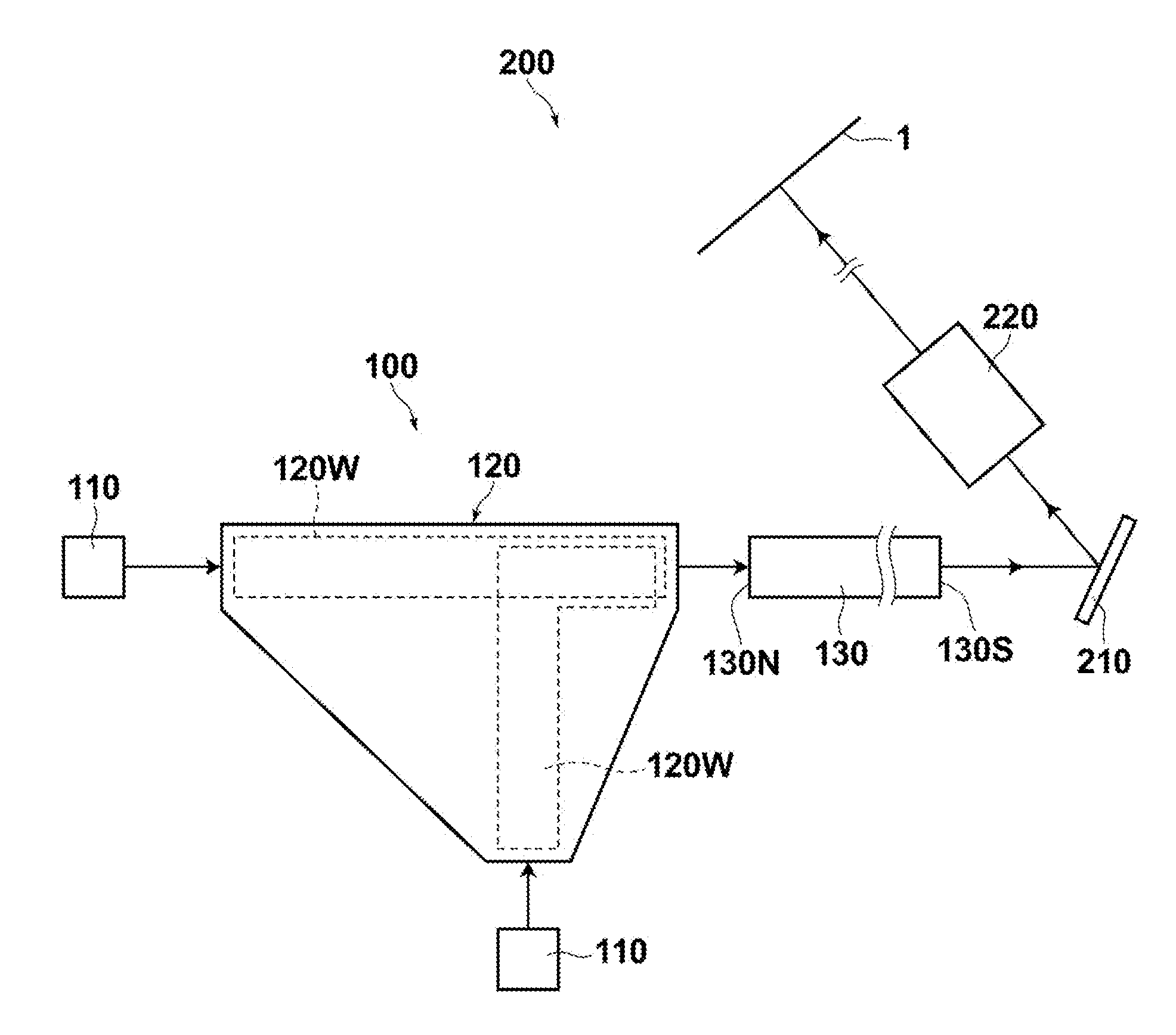
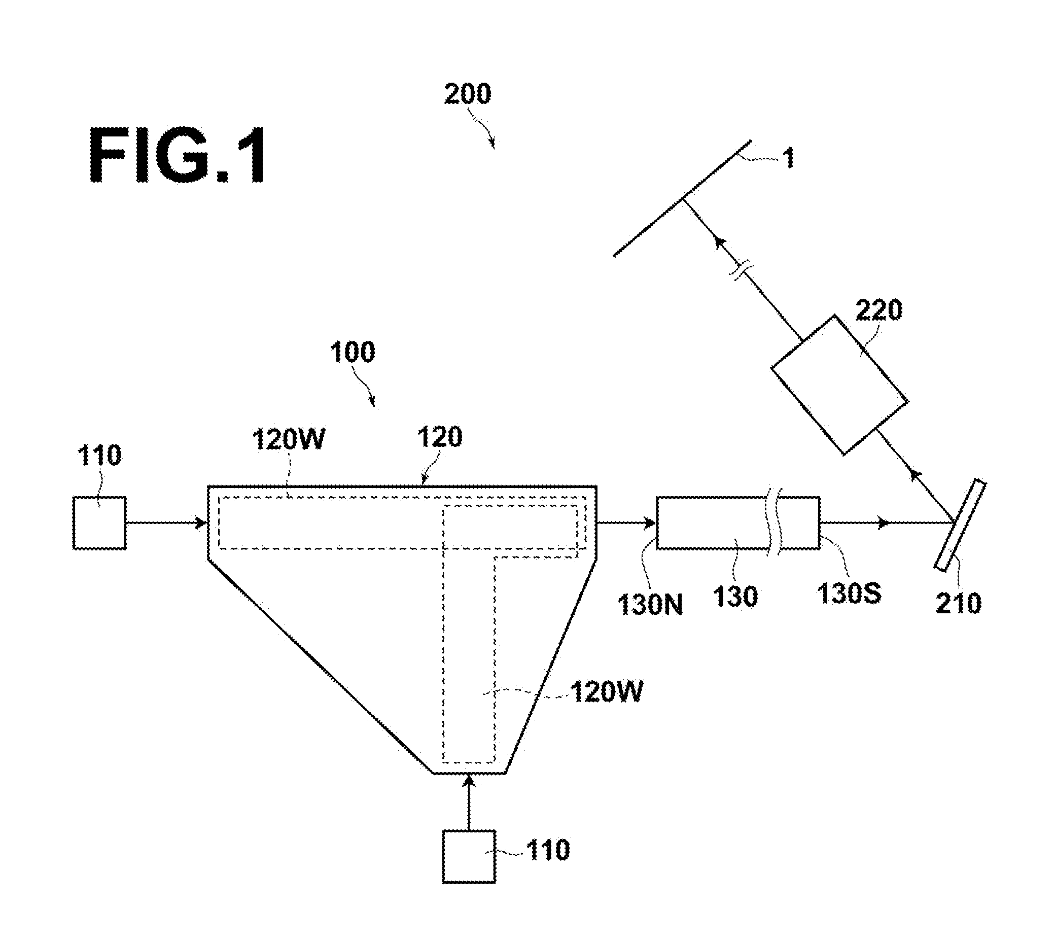
  • Illuminating optical system and projection display apparatus
  • Illuminating optical system and projection display apparatus
  • Illuminating optical system and projection display apparatus

Examples


example 1

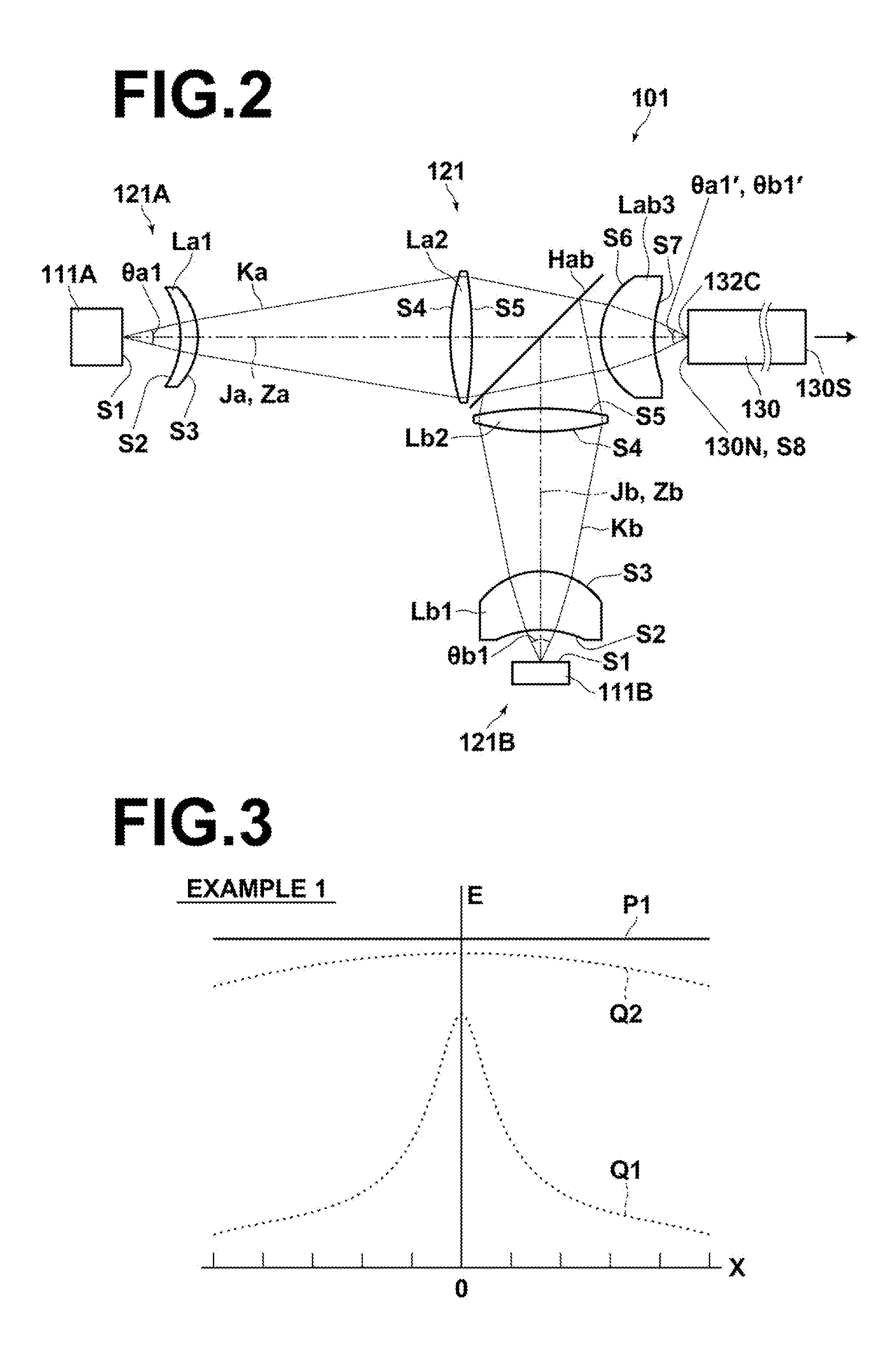
[0083]FIG. 2 is a sectional diagram that illustrates an illuminating optical system of Example 1. Example 1 is an illuminating optical system having a total of two light sources including one each of two types of light sources.

[0084]The illuminating optical system 101 of Example 1 illustrated in FIG. 2 has a first light source 111A and a second light source 111B, which are two different types of light sources, and a light combining optical system 121 that combines light beams output from the two light sources and causes them to converge at a single position.

[0085]Further, the illuminating optical system 101 is equipped with a rod integrator 130a that uniformizes the light intensity distributions of the light beams which are converged at the single position that enter a light input surface 130N at one end thereof and outputs a light beam, of which the light intensity distribution has been uniformized, from a light output surface 130S at a second end thereof.

[0086]The light combining ...

example 2

[0107]Next, Example 2 will be described.

[0108]FIG. 4 is a sectional diagram that illustrates an illuminating optical system 102 of Example 2. Note that constituent elements of Example 2 which are the same as those of Example 1 are denoted by the same reference numerals, and detailed descriptions thereof will be omitted.

[0109]The illuminating optical system 102 of Example 2 has a total of four light sources including two first light sources 112C of a first type, and two second light sources 112D of a second type.

[0110]Note that the light sources of the same type are those having at least light emitting regions of the same size, the same spreading angles of light beams output therefrom, and the same colors.

[0111]A light combining means 122 combines light beams output from the two first light sources 112C and the two second light sources 112D, and causes them to converge at a single position.

[0112]The light beams which are converged at the single position are caused to enter the rod in...

example 3

[0127]Next, Example 3 will be described.

[0128]FIG. 6 is a sectional diagram that illustrates an illuminating optical system 103 of Example 3. Note that constituent elements of Example 3 which are the same as those of Example 1 are denoted by the same reference numerals, and detailed descriptions thereof will be omitted.

[0129]The illuminating optical system 103 of Example 3 has a total of three light sources of three different types, which are a first light source 113E, a second light source 113F, and a third light source 113G.

[0130]A light combining means 123 combines light beams output from the first light source 113E, the second light source 113F, and the third light source 113G, and causes them to converge at a single position.

[0131]The light beams which are converged at the single position are caused to enter the light input surface 130N of the rod integrator 130.

[0132]The light combining optical system 123 has a first relay optical component set 123E that relays a light beam Ke...


PUM


Abstract

An illuminating optical system suppresses deterioration in utilization efficiency of illuminating light and generation of fluctuations in light emission without increasing apparatus size. The illuminating optical system includes a plurality of light sources of different types, a light combining optical system that combines light beams output from each of the light sources such that they converge at a single position, and a rod integrator that uniformizes the light intensity distributions of the light beams which are converged at the single position that enter a first end thereof and outputs the light beams, of which the light intensity distribution has been uniformized, from a second end thereof. The light combining optical system includes relay optical component sets corresponding to each of the light sources, and the relay optical component sets have relay magnification ratios different from each other.

Description

CROSS REFERENCE TO RELATED APPLICATIONS[0001]This application is a continuation of PCT / JP2012 / 000874 filed on Feb. 9, 2012, which claims foreign priority to Japanese Application No. 2011-027001 filed on Feb. 10, 2011. The entire contents of each of the above identified applications are hereby incorporated by reference.BACKGROUND OF THE INVENTION[0002]1. Field of the Invention[0003]The present invention is related to an illuminating optical system and a projection display apparatus. More specifically, the present invention is related to an illuminating optical system that passes light output from light sources through a rod integrator to uniformize the distribution of light intensity and outputs the uniformized light, and a projection display apparatus that employs the illuminating optical system.[0004]2. Description of the Related Art[0005]Conventionally, there are known projection display apparatuses that modulate light beams output by light sources with light modulating elements s...

Claims


Application Information

Patent Timeline
Patent Type & Authority Applications(United States)
IPC IPC(8): G03B21/20F21K99/00F21V8/00
CPCG03B21/208G02B6/0096F21K9/52G02B6/0001F21K9/61G02B27/0905G02B27/0994G03B21/2013G03B21/2033H04N9/3152
Inventor YAMAMOTO, CHIKARA
Owner FUJIFILM CORP
Learn More