Eureka AIR delivers breakthrough ideas for toughest innovation challenges, trusted by R&D personnel around the world.

Adjustable Guard Assembly for a Sickle Knife

Inactive Publication Date: 2013-11-21
MACDON INDS
View PDF10 Cites 10 Cited by
  • Summary
  • Abstract
  • Description
  • Claims
  • Application Information

AI Technical Summary

Benefits of technology

The patent text describes an adjustment screw that can be used to change the spacing between a hold down member and a support bar. This is done by adjusting the amount of compression of a compressible resilient pad, which can affect the alignment of components in a device. The technical effect of this invention is improved accuracy and precision in the alignment of components in a device.

Problems solved by technology

However this technique is an inaccurate, inconvenient and time consuming process which must be regularly repeated during routine maintenance of the equipment in view of wear which occurs between the knife arrangement and the stub guards.

Method used


Image

  • Adjustable Guard Assembly for a Sickle Knife
  • Adjustable Guard Assembly for a Sickle Knife
  • Adjustable Guard Assembly for a Sickle Knife

Examples


Embodiment Construction

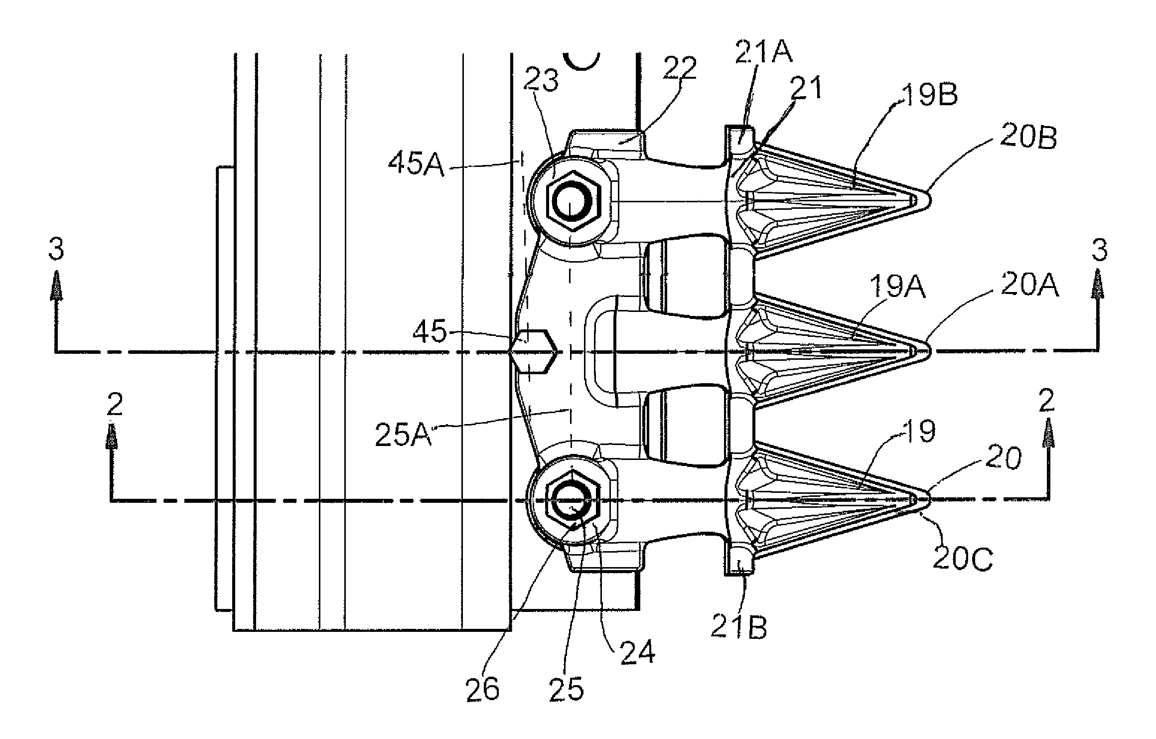
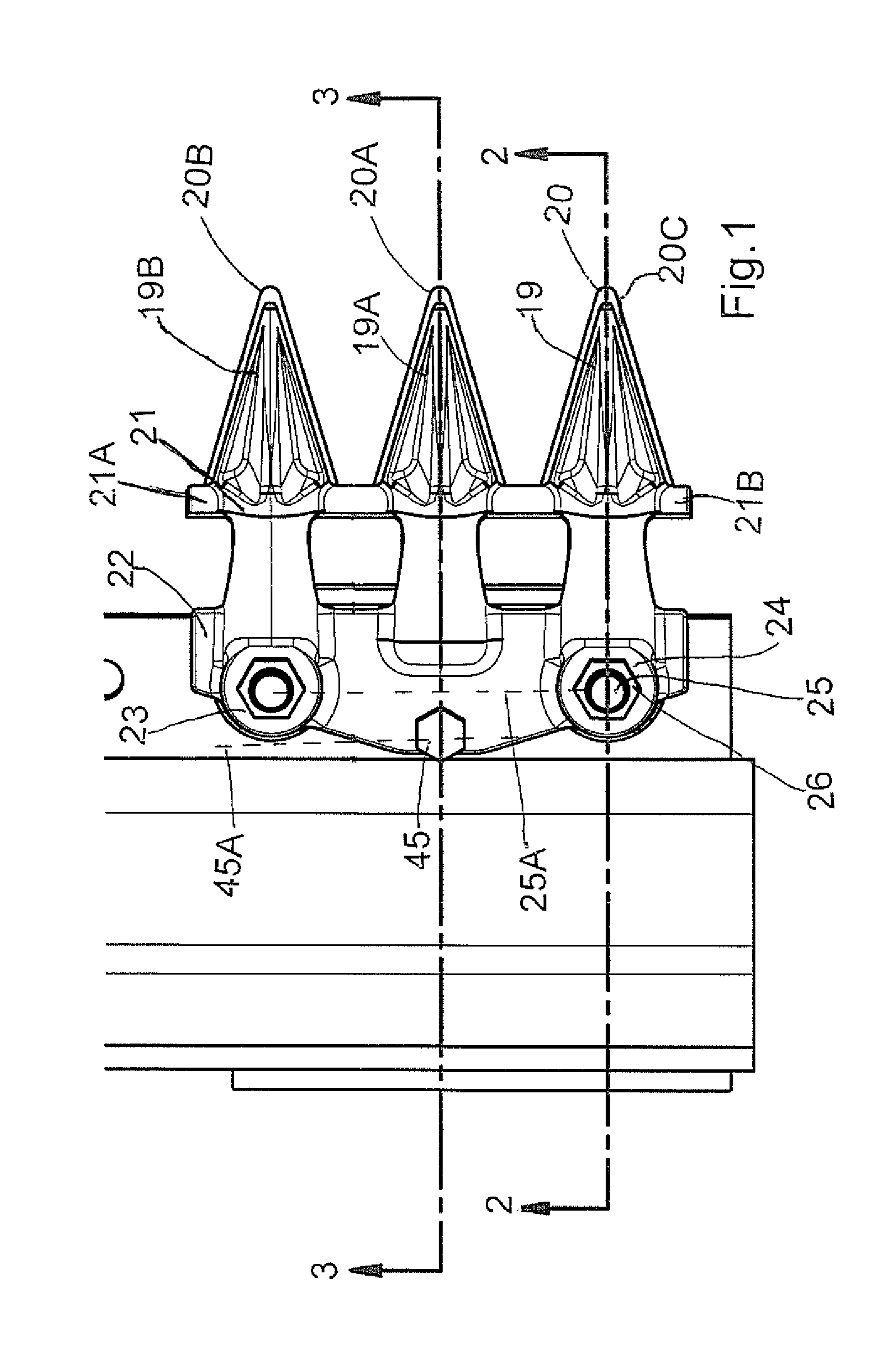
[0071]The crop cutting apparatus shown in FIGS. 1 and 2 comprises a frame member 10 only a part of which is shown since this is of conventional construction. The attachment of the frame to suitable ground wheels and a suitable traction unit are not shown as these are of a conventional nature and are not involved in the present invention. The frame 10 carries a support flange or support bar 11 which projects forwardly from the frame and extends in a horizontal plane across a front surface of the frame. The flange or support bar is shown attached by weld lines 12 but this is one example only of the mounting techniques since the flange itself is again of a conventional structure. The flange extends along substantially the full width of the frame so as to carry the sickle knife described in more detail hereinafter.

[0072]As well known by one skilled in the art, the support bar 11 carries a plurality of stub guards or knife guards, arranged in side by side relation across the full length ...


PUM


Abstract

In a cutter bar having a upper and lower knife guards in cooperating pairs mounted on a support bar where each guard includes at least one point extending forwardly to define a channel therebetween in which the knife reciprocates, the upper knife guards are attached to an upper surface of the support bar by a compressible resilient pad between an under surface of the upper knife guard and the upper surface of the support bar, at least one hold down screw fastener engaged between the upper knife guard and the support bar which holds the upper knife guard on to the resilient pad and forms a fulcrum and at least one adjustment screw between the upper knife guard and the support bar behind the screw fastener so that adjustment of the screw increases an amount of compression of the compressible resilient pad.

Description

[0001]This application claims the benefit under 35 USC 119(e) of Provisional Application 61 / 577,427 filed Dec. 19, 2011.[0002]This invention relates to an adjustable guard assembly for the sickle knife of a crop cutting apparatus such as a swather or combine harvester.BACKGROUND OF THE INVENTION[0003]The cutting knife of a crop cutting apparatus of the type with which the present invention is concerned generally comprises a horizontal support bar or flange supported on the apparatus for movement across the ground in a cutting action. On the support bar is mounted a plurality of guards with one guard section clamped above the support bar as a hold down and the other guard section providing a ledger surface for the knife blades clamped below the support bar.[0004]Generally each lower guard section is formed as an integral cast body defining a one, two, three or more of forwardly projecting fingers which are connected by transverse bars.[0005]The lower guard section can be of the type ...

Claims


Application Information

Patent Timeline
IPC IPC(8): A01D34/13
CPCA01D34/13A01D34/16A01D34/18
Inventor TALBOT, FRANCOIS R.REMILLARD, RHEAL G.
Owner MACDON INDS
Why Eureka
Eureka Blog
Learn More