
Enhanced medical device for use in bodily cavities, for example an atrium

a medical device and atrium technology, applied in the field of surgery, can solve the problems of increasing the complexity of the device structure, affecting the patient's clinical experience, and doctors not having direct visual contact with the medical device,

Active Publication Date: 2013-11-14
KARDIUM
View PDF9 Cites 88 Cited by
  • Summary
  • Abstract
  • Description
  • Claims
  • Application Information

AI Technical Summary

Benefits of technology

Enables enhanced deployment, positioning, and ablation capabilities within cardiac cavities, improving the accuracy and effectiveness of treatments by allowing precise alignment with anatomical features and reducing the risk of adverse results.

Problems solved by technology

However, the use of intravascular or percutaneous technologies also raises some particular challenges.
Medical devices used in intravascular or percutaneous surgery need to be deployed via catheter systems which significantly increase the complexity of the device structure.
As well, doctors do not have direct visual contact with the medical devices once the devices are positioned within the body.
Positioning these devices correctly and operating the devices successfully can often be very challenging.
The procedure is performed with a high success rate under the direct vision that is provided in open procedures, but is relatively complex to perform intravascularly or percutaneously because of the difficulty in creating the lesions in the correct locations.
Various problems, potentially leading to severe adverse results, may occur if the lesions are placed incorrectly.
Additional challenges therefore exist in creating a device that can assume an unexpanded configuration for passage through these smaller sheaths and yet, can also assume an expanded configuration suitable for positioning a portion of the device proximate to a tissue surface within the cavity.

Method used


Image

  • Enhanced medical device for use in bodily cavities, for example an atrium
  • Enhanced medical device for use in bodily cavities, for example an atrium
  • Enhanced medical device for use in bodily cavities, for example an atrium

Examples


Embodiment Construction

[0205]In the following description, certain specific details are set forth in order to provide a thorough understanding of various embodiments of the invention. However, one skilled in the art will understand that the invention may be practiced without these details. In other instances, well-known structures associated with Radio Frequency (RF) ablation and electronic controls such as multiplexers have not been shown or described in detail to avoid unnecessarily obscuring descriptions of the embodiments of the invention.

[0206]The word “ablation” should be understood to mean any disruption to certain properties of the tissue. Most commonly, the disruption is to the electrical conductivity and is achieved by heating, which can be generated with resistive or of Radio Frequencies (RF) techniques for example. Other properties, such as mechanical or chemical, and other means of disruption, such as optical, are included when the term “ablation” is used.

[0207]The word “fluid” should be unde...


PUM


Abstract

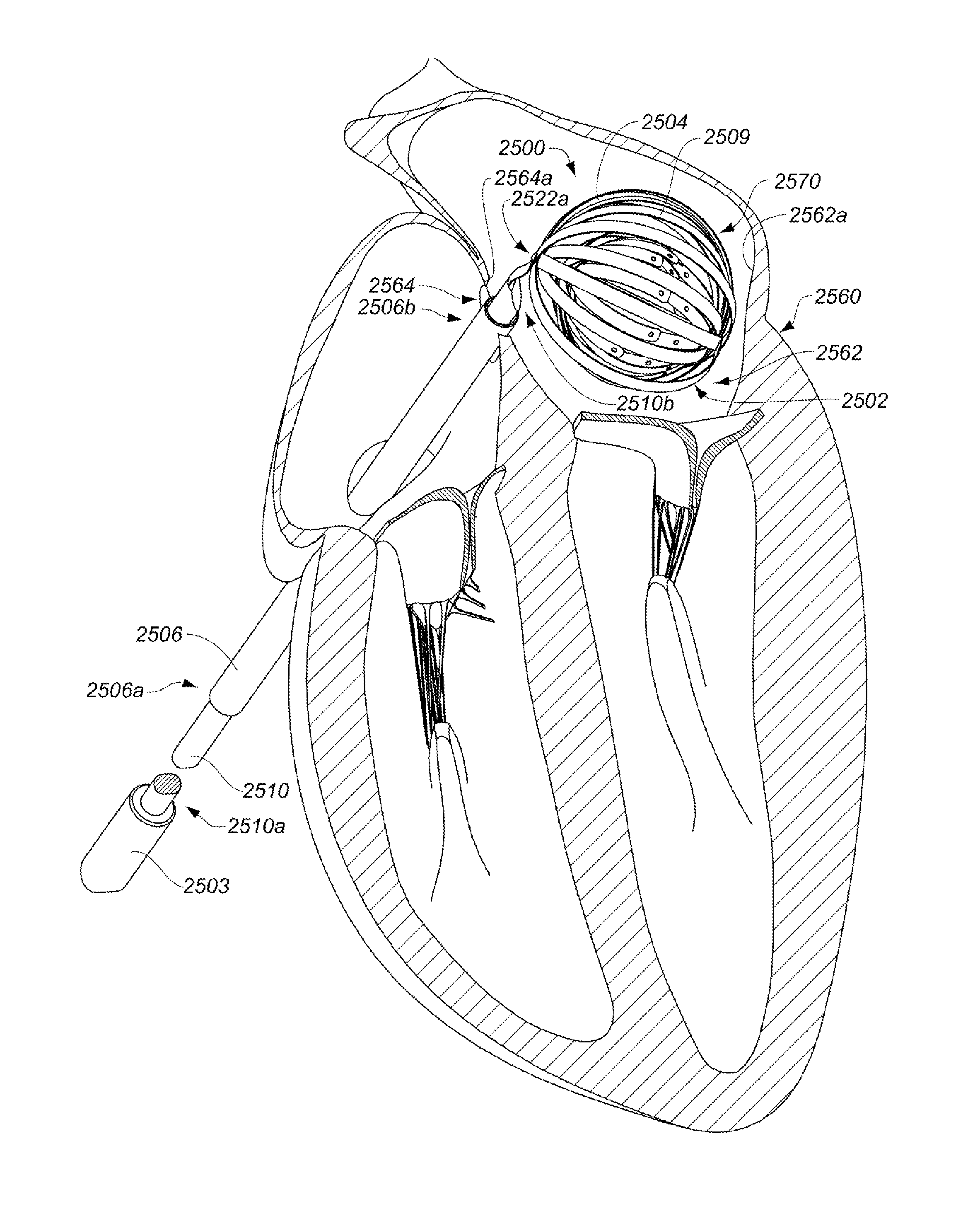
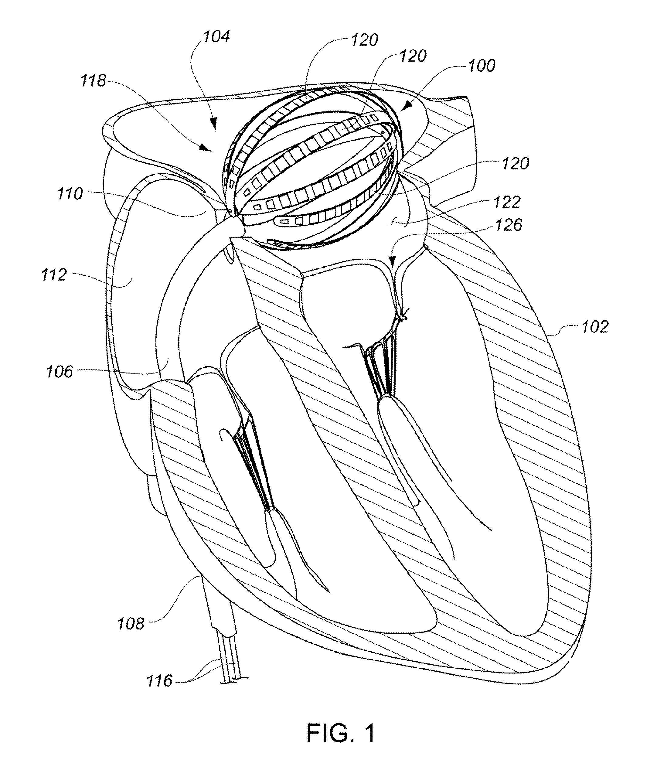
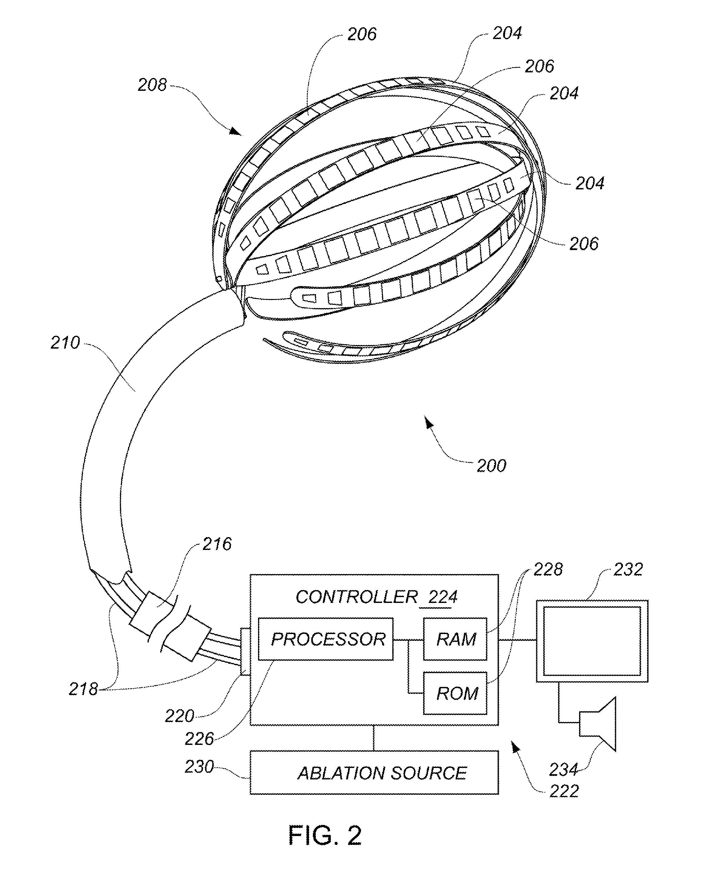
Systems, methods, and devices allow intravascular or percutaneous mapping, orientation or ablation, or combinations thereof in bodily cavities or lumens. A device includes a plurality of elongate members which are moveable between an unexpanded configuration, a bent or coiled stack configuration and an expanded or fanned configuration. The elongate members form a stack arrangement in the unexpanded configuration to fit through a catheter sheath. The elongate members follow respective arcuate or curvilinear paths as advanced from the sheath into the bent or coiled stack configuration, adopting volute, scroll or rho shapes, and may be nested. The elongated members are fanned or radially spaced circumferentially with respect to one another into the expanded or fanned configuration. Transducers carried by elongate members may sense various physiological characteristics of or proximate tissue, for instance temperature, and / or may apply energy to or proximate tissue, for example to perform ablation. The device is retractable.

Description

CROSS-REFERENCE TO RELATED APPLICATIONS[0001]This application: is a continuation of prior International Application No. PCT / US2012 / 022061, which has an international filing date of Jan. 20, 2012, and which claims the benefit of each of U.S. Provisional Application No. 61 / 435,213, filed Jan. 21, 2011; U.S. Provisional Application No. 61 / 485,987, filed May 13, 2011; U.S. Provisional Application No. 61 / 488,639, filed May 20, 2011; and U.S. Provisional Application No. 61 / 515,141, filed Aug. 4, 2011. The entire disclosure of each of the applications cited in this Cross-Reference to Related Applications Section is hereby incorporated herein by reference.BACKGROUND[0002]1. Technical Field[0003]This disclosure is generally related to surgery, and more particularly to intravascularly or percutaneously deployed medical devices suitable for determining locations of cardiac features or ablating regions of cardiac tissue, or both.[0004]2. Description of the Related Art[0005]Cardiac surgery was i...

Claims


Application Information

Patent Timeline
Patent Type & Authority Applications(United States)
IPC IPC(8): A61B18/14
CPCA61B18/1492A61B5/0538A61M25/0074A61M25/0082A61B5/6843A61B5/6858A61B5/026A61B2018/0016A61B2018/00267A61B2018/00351A61B2018/00357A61B2018/00577A61B2018/00791A61B2018/00839A61B2018/00863A61B2018/00875A61B2090/065A61B5/065A61B5/287A61B5/06A61B18/00
Inventor LOPES, FERNANDO LUIS DE SOUZAMOISA, SAARJARAMILLO, JORGEGOERTZEN, DOUGLAS WAYNEHAWES, PETER JOSIAHSARDARI, ASHKANSALVESTRO, ALDO ANTONIO
Owner KARDIUM
Learn More