Traction-means tensioning device having a securing element, and internal combustion engine having such a traction-means tensioning device

Inactive Publication Date: 2013-11-14
SCHAEFFLER TECH AG & CO KG
View PDF26 Cites 14 Cited by
  • Summary
  • Abstract
  • Description
  • Claims
  • Application Information

AI Technical Summary

Benefits of technology

The present invention relates to a device for tensioning traction means in internal combustion engines. The invention includes a slide sleeve that has to be secured to prevent it from moving out axially and to ensure a pretensioning force even at different temperatures. The device also uses a press-in part with toothing and a resilient head piece to induce self-locking and compensate for temperature fluctuations and length tolerances. The technical effect of the invention is to provide a reliable and efficient device for tensioning traction means in engines.

Problems solved by technology

However, using known methods, it is still difficult, on the one hand, to both secure the sleeve in which the hydraulically extendable piston is supported and, on the other hand, compensate for elongations induced by the different materials selected for the housing, sleeve and piston.
It is, in fact, known to use an alignment pin, respectively tolerance rings to hold the sleeve; the alignment pin or the tolerance rings causing a deformation of the hydraulic element, thus the sleeve, which, however, degrades the performance of the hydraulic element.
There are even significant inherent disadvantages to otherwise customary approaches, such as securing by pressing in place and by bonding.
Thus, the disadvantage of the pressing-in-place approach is that substantial overlapping is required to allow forces to be transferred both at low temperatures, such as −40° C., as well as at high temperatures, such as 150° C. This is due, in particular, to the different expansion coefficients of aluminum and steel.

Method used


Image

  • Traction-means tensioning device having a securing element, and internal combustion engine having such a traction-means tensioning device
  • Traction-means tensioning device having a securing element, and internal combustion engine having such a traction-means tensioning device
  • Traction-means tensioning device having a securing element, and internal combustion engine having such a traction-means tensioning device

Examples


Embodiment Construction

[0032]The figures are merely schematic and serve exclusively to further the understanding of the present invention. The elements having essentially equivalent functions are denoted by the same reference numerals.

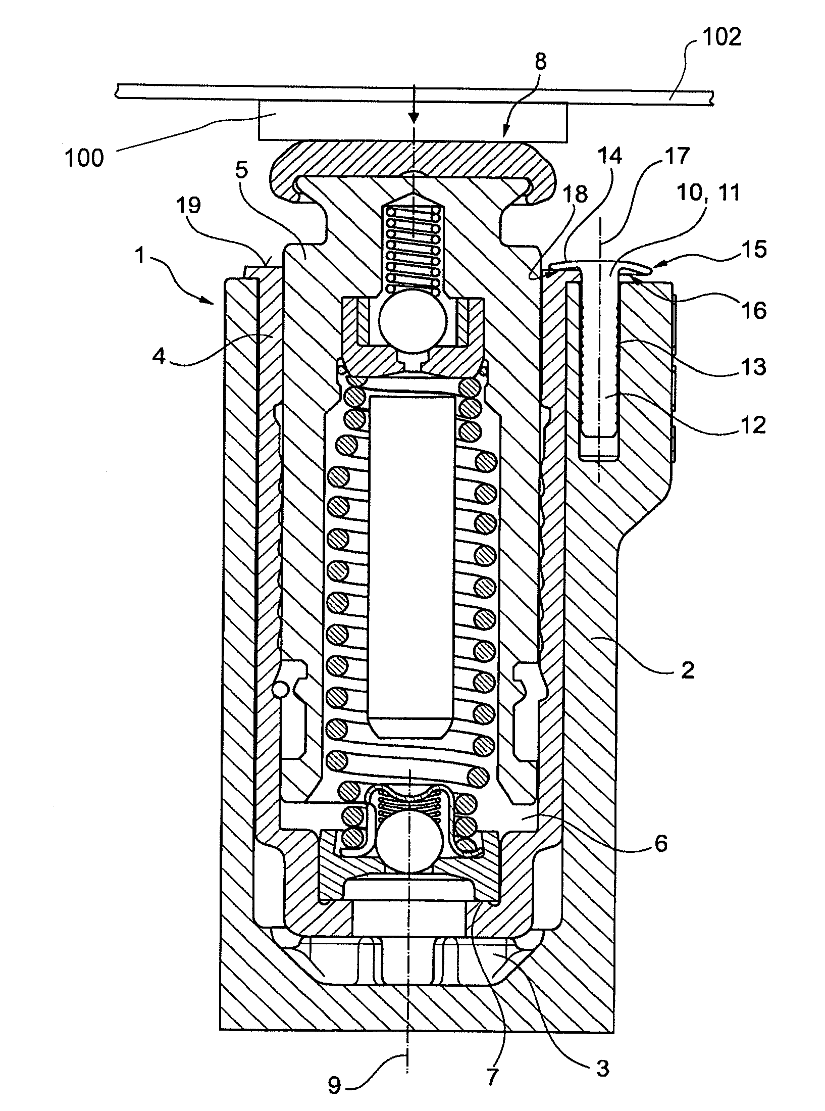
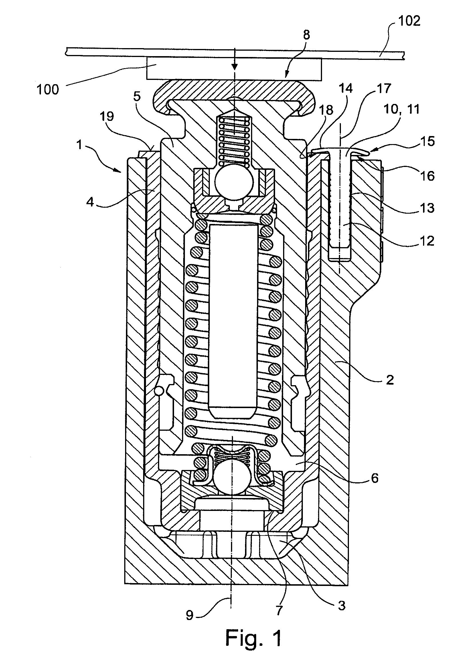
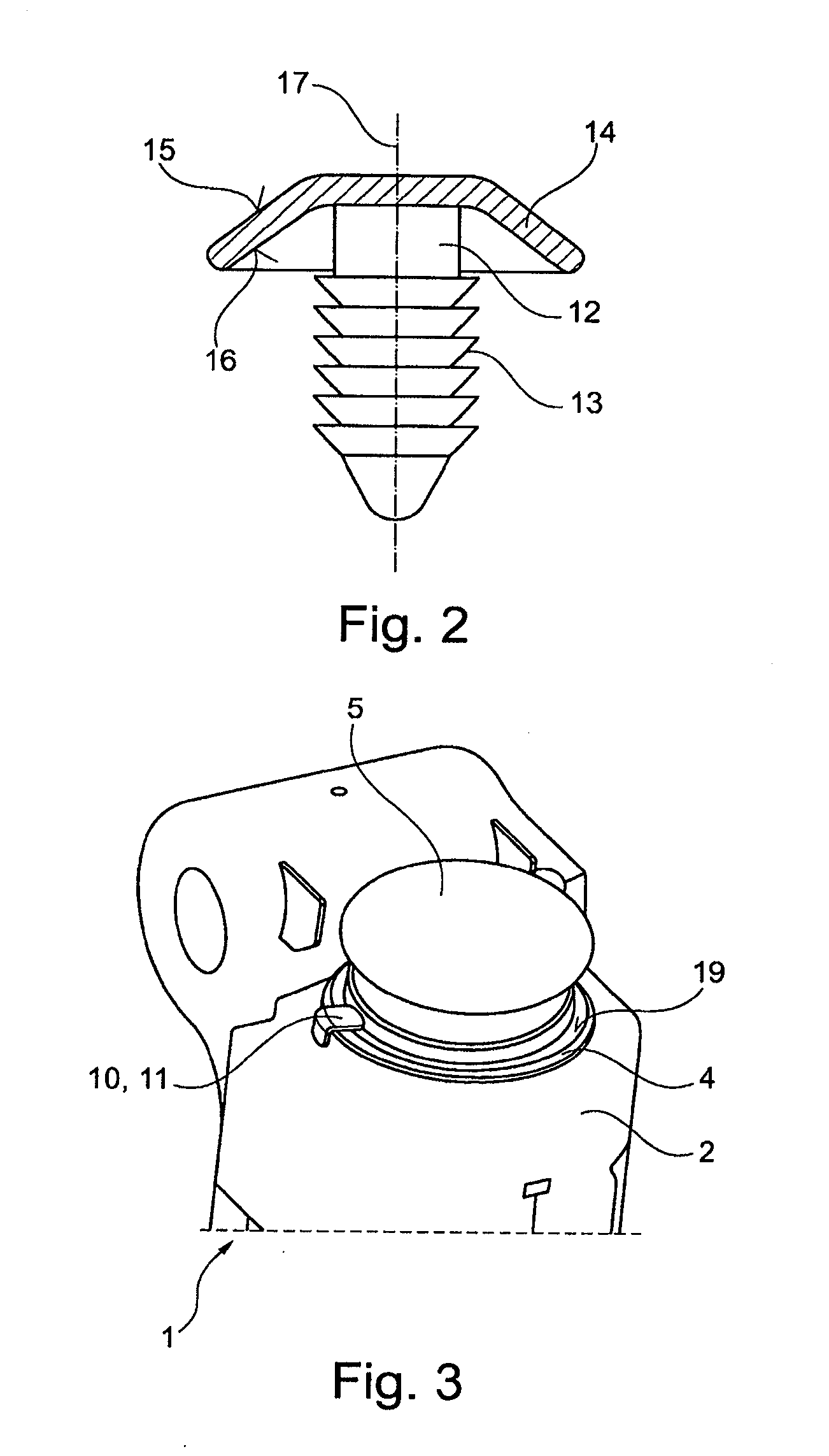
[0033]FIG. 1 shows a section through a traction-means tensioning device 1 according to the present invention.

[0034]Traction-means tensioning device 1 has a housing 2. Housing 2 is manufactured from aluminum, respectively an aluminum alloy. Die-cast aluminum, in particular, is used for housing 2.

[0035]Housing 2 has a bore 3 which features a substantially cylindrical cross section. A slide sleeve 4 is inserted into bore 3. Slide sleeve 4 is inserted essentially axially immovably in housing 2 and is also configured in bore 3 essentially non-rotatably relative to housing 2. In the interior thereof, slide sleeve 4 has a piston 5 that is slidingly configured to be extendable therefrom. Slide sleeve 4 is manufactured of steel.

[0036]Located in the interior of slide sleeve 4 is a pre...


PUM


Abstract

A traction-means tensioning device having a housing that contains aluminum as a material, into which a slide sleeve is inserted axially immovably, within which a hydraulically actuatable, axially extendable piston is supported; a pressure chamber being provided between the piston, which is made of steel, and the slide sleeve, which is made of steel, that can be filled with a hydraulic medium; a securing element engaging on the slide sleeve and the housing to fix the axial position of the slide sleeve relative to the housing, the securing element being provided with an elongate fastening portion that is configured to be fixed in position in the housing and is provided at a housing-distal end with a head that is in form-fitting contact with the slide sleeve. Also, an internal combustion engine having such a traction-means tensioning device and a traction means.

Description

[0001]The present invention relates to a traction-means tensioning unit having a housing that contains aluminum as a material, into which a slide sleeve is inserted axially immovably, within which a hydraulically actuated, axially extendable piston is supported; a pressure chamber being provided between the piston that is made of steel and the slide sleeve that is made of steel which can be filled with a hydraulic medium; a securing element engaging on the slide sleeve and the housing to fix the axial position of the slide sleeve relative to the housing.BACKGROUND[0002]Traction-means tensioning devices are used in traction-means drives of internal combustion engines. Such traction-means drives employ either belts, such as toothed belts, or chains, such as timing chains, as traction means. Such traction-means drives are used, in particular, for timing drives of internal combustion engines. Additionally or alternatively, they can also drive other aggregates, such as generators or elec...

Claims


Application Information

Patent Timeline
IPC IPC(8): F16H7/08
CPCF16H7/08F16H7/0836F16H2007/0806F16H2007/0812F16H2007/0859F16H2007/0878
Inventor HOFMANN, DOMINIKTYROLLER, PETER
Owner SCHAEFFLER TECH AG & CO KG
Why Eureka
Try Eureka