System for detecting misalignment of an aero surface

Inactive Publication Date: 2013-11-14
AIRBUS OPERATIONS LTD
View PDF10 Cites 5 Cited by
  • Summary
  • Abstract
  • Description
  • Claims
  • Application Information

AI Technical Summary

Benefits of technology

The invention is a system that is easy to install, uses less power than other options, and requires minimal adjustment. It is also less sensitive to changes in temperature and is more affordable to manufacture. These technical effects make it a good choice for a wide range of applications.

Problems solved by technology

If a misalignment occurs, the holes in adjacent aero surfaces will fall out of alignment resulting in cutting of the light beam.

Method used


Image

  • System for detecting misalignment of an aero surface
  • System for detecting misalignment of an aero surface
  • System for detecting misalignment of an aero surface

Examples


Embodiment Construction

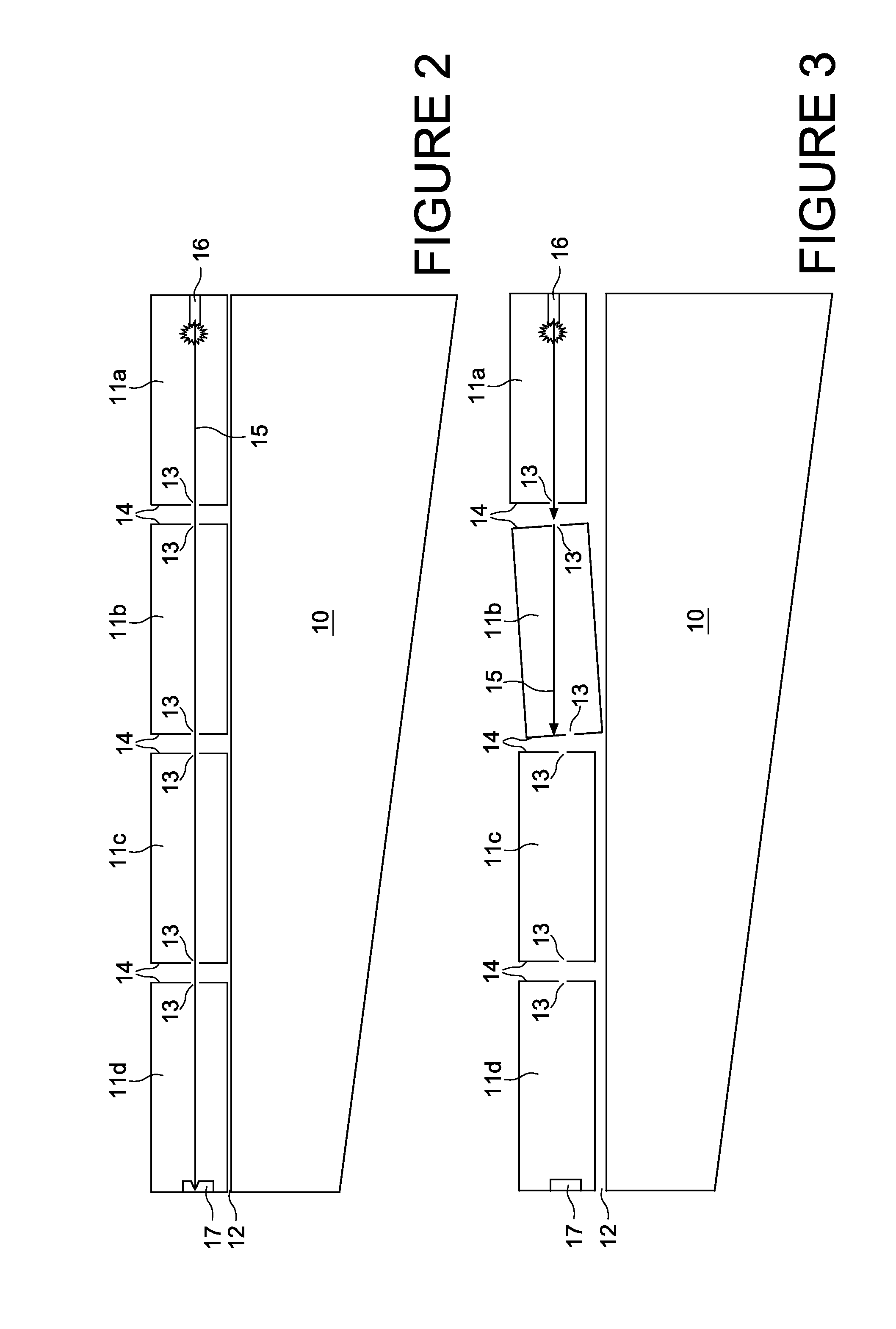
[0029]Referring first to FIG. 2, there is shown a simplified plan view of an aircraft wing 10 having a plurality of slats 11a-11d along its leading edge 12.

[0030]Each slat has a hole 13 in each of its end walls 14 where it faces and end wall 14 of an adjacent slat 11 so that a light beam, such as a laser 15, generated by a laser light generator 16 mounted within the innermost slat 11a closest to the fuselage (not shown) can pass through all of the apertures and reflect back off a reflector 17 mounted within the outermost slat 11d, furthest away from the fuselage. The receptor is integral with the laser light generator 16 to detect the light reflected back through the apertures 13, which has the advantage of being small and light weight and of low power consumption, although it will be appreciated that the receptor may be an entirely separate component.

[0031]Although only one laser light generator 16 is shown in the drawings, it will be appreciated that two or more light generators 1...


PUM


Abstract

A system for detecting misalignment of an aero surface relative to other aero surfaces during simultaneous deployment of said aero surfaces is disclosed. It comprises a generator configured to shine a laser through aligned apertures in a series of aero surfaces towards a reflector during deployment of said aero surfaces, a receptor to detect reflection of said laser from said reflector back through said apertures to the generator and, a controller operable to terminate further deployment of said aero surfaces in the event that no reflection is detected by said receptor, or if an actual time taken for the reflected beam of light to be detected by the receptor differs from a predetermined time. In a preferred embodiment the aero sufaces are slats extending from the leading edge of an aircraft wing.

Description

INTRODUCTION[0001]The present invention relates to a system for detecting misalignment of an aero surface of a number of aero surfaces on an aircraft that are mechanically synchronised under normal conditions such that they extend and retract together with parallel motion. Such moving surfaces may be the slats extending from the leading edge of a wing of an aircraft, although the system of the invention may also be used in conjunction with other moving surfaces. A method of detecting misalignment in aero surfaces is also disclosed.BACKGROUND[0002]Aircraft need to produce varying levels of lift for take-off, landing and cruise. A combination of wing leading and trailing edge devices are used to control the wing coefficient of lift. The leading edge device is known as a slat. On larger aircraft there may be several slats spaced along the wing edge. During normal flight the slats are retracted against the leading edge of the wing. However, during take-off and landing they are deployed ...

Claims


Application Information

Patent Timeline
IPC IPC(8): G01B11/14
CPCG01B11/14B64D45/0005B64D2045/001
Inventor TEAGUE, PHILLIP VINCENT
Owner AIRBUS OPERATIONS LTD
Why Eureka
Try Eureka