
Vehicle seat

a technology for vehicles and seats, applied in the field of vehicles, can solve the problems of difficult air passages and air passages to be squashed, and achieve the effect of superior blowing performance and better ride quality

Active Publication Date: 2013-11-14
TOYOTA BOSHOKU KK
View PDF16 Cites 28 Cited by
  • Summary
  • Abstract
  • Description
  • Claims
  • Application Information

AI Technical Summary

Benefits of technology

The present invention aims to provide an air passage in a pad to improve its ventilating function without compromising its comfortable supporting property during sitting. The air passage is formed at a position avoiding the high-load portion of the pad, reducing the likelihood of it being squashed by pressure. This results in better supporting quality for the occupant and improved ride quality. The air passage can also be provided to come at the installation area of the supporting spring to further enhance the supporting property and ventilating function. Additionally, the air passage can be provided along the outer circumferential edge of the high-load portion of the pad, making it easier to send air to the occupant's body. Overall, the invention provides a solution to improve the air passage in pads to optimize their ventilating function.

Problems solved by technology

Therefore, even if the body pressure of the occupant is applied to the pad, it is difficult for the air passage to be squashed.
However, since the air passage is formed at a position avoiding the high-load portion, it is difficult for the air passage to be squashed.

Method used


Image

  • Vehicle seat
  • Vehicle seat
  • Vehicle seat

Examples


Embodiment Construction

[0023]Hereinafter, illustrative embodiments of the present invention will be described with reference to the accompanying drawings.

First Illustrative Embodiment

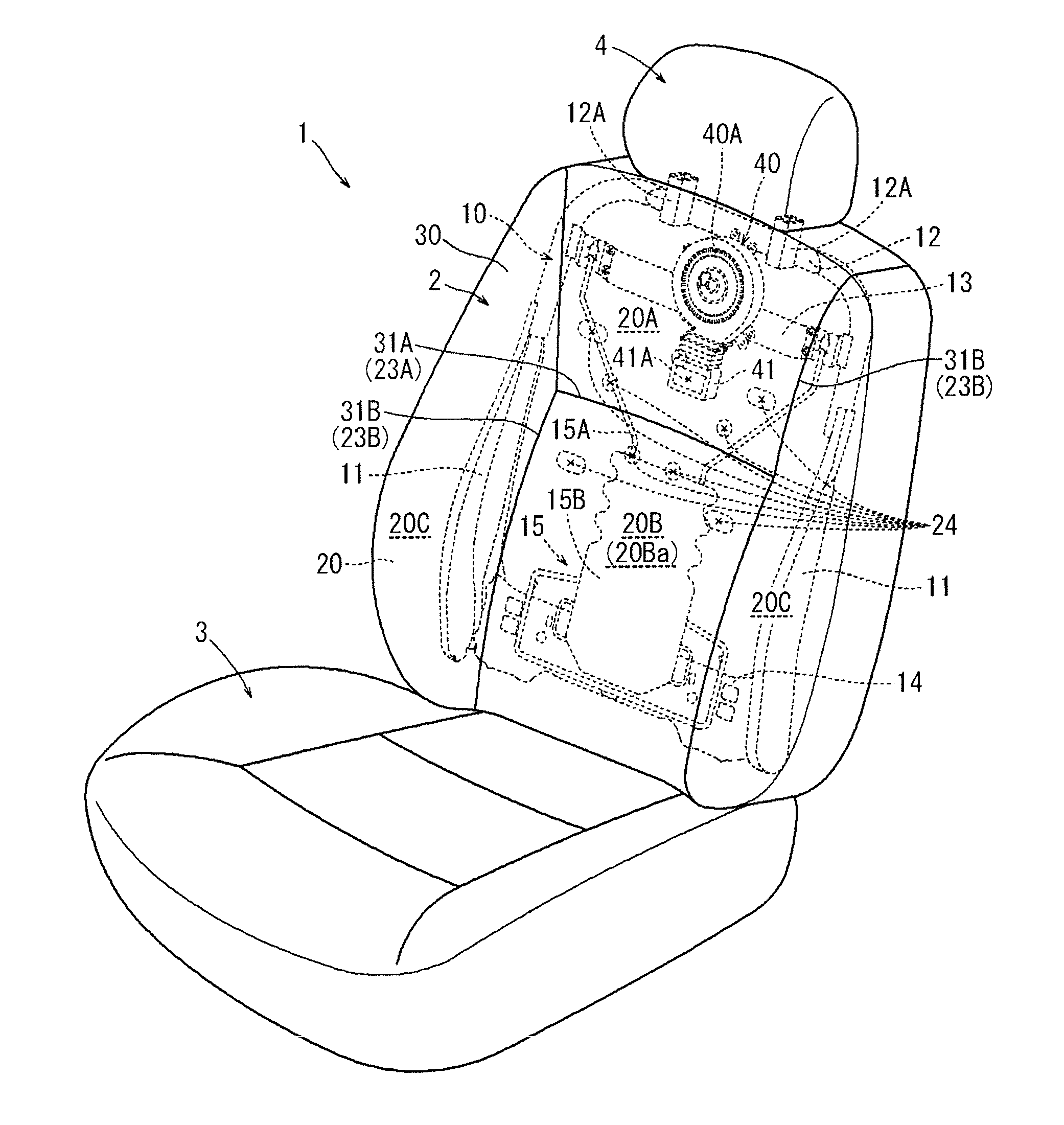
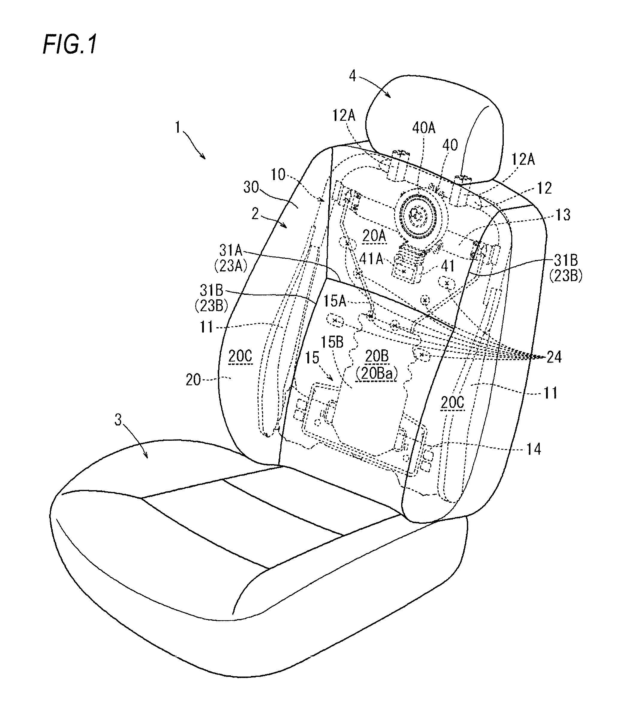
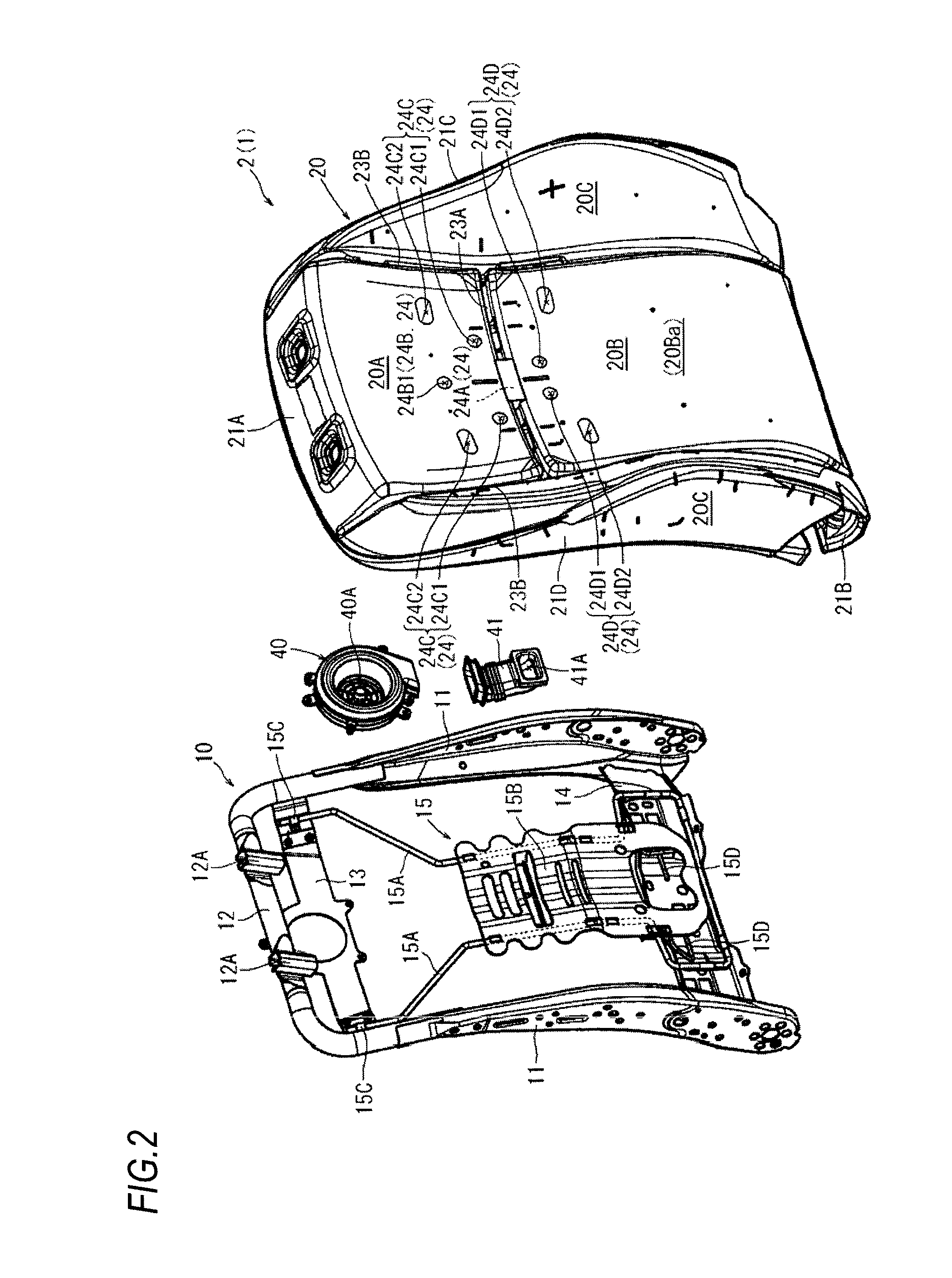
[0024]First, a configuration of a vehicle seat 1 according to a first illustrative embodiment will be described with reference to FIGS. 1 to 6. As shown in FIG. 1, the vehicle seat 1 according to the present illustrative embodiment is disposed as a driver's seat of an automobile, and includes a seat back 2 which functions as a backrest for an occupant, a seat cushion 3 which functions as a seating portion, and a headrest 4 which functions as a rest for a head. As shown in FIG. 2, the seat back 2 includes a centrifugal fan 40 which is disposed in the seat back 2 and can discharge air from an inside to a back of the occupant. Further, the seat back 2 includes an air passage 24 which is formed in a rear surface of a back pad 20 which functions as an internal cushion material and allows air from the fan 40 to flow dispersively an...


PUM


Abstract

There is provided a vehicle seat having an air passage formed to extend in an in-plane direction in a pad for supporting a body of an occupant. The vehicle seat includes a seat frame which supports a peripheral portion of the pad from a rear side thereof; and a support body which is supported by the seat frame and is configured to elastically support, from a rear side, a high-load portion of a center of the pad on which a body pressure of the occupant is concentrated, wherein the air passage is formed at a position avoiding the high-load portion of the pad supported by the support body.

Description

BACKGROUND OF THE INVENTION[0001]1. Field of the Invention[0002]The present invention relates to a vehicle seat. Specifically, the present invention relates to a vehicle seat including an air passage formed to extend in an in-plane direction in a pad for supporting a body of an occupant.[0003]2. Description of Related Art[0004]There has been known a vehicle seat having a fan for sending air from a rear side to a body of an occupant through a pad (see, for example, JP-A-2002-17510). In this vehicle seat, in order to distribute air from the fan broadly in an in-plane direction on a rear surface side of the pad such that the air can be sent into the pad, a plurality of hollow air passages are formed to extend in the in-plane direction in a rear surface of the pad.[0005]However, in the above related-art technique, the air passages are provided in an installation area of a supporting spring suspended between seat frames, and particularly, provided in an installation area of the supportin...

Claims


Application Information

Patent Timeline
IPC IPC(8): B60N2/56
CPCB60N2/5664B60N2/5635B60N2/5657B60N2/66B60N2/56B60N2/5621B60N2/5642
Inventor OTA, HIROKI
Owner TOYOTA BOSHOKU KK
Learn More