Method for operating a vertical packaging machine and vertical packaging machine
a technology of vertical packaging machine and packaging machine, which is applied in the direction of packaging goods type, transportation and packaging, liquid materials, etc., can solve the problems of different sizes of packaging, and achieve the effects of avoiding slippage, preventing slippage or the risk of slippage, and improving the drive of advance modules on the laminar film
- Summary
- Abstract
- Description
- Claims
- Application Information
AI Technical Summary
Benefits of technology
Problems solved by technology
Method used
Image

Examples
first embodiment
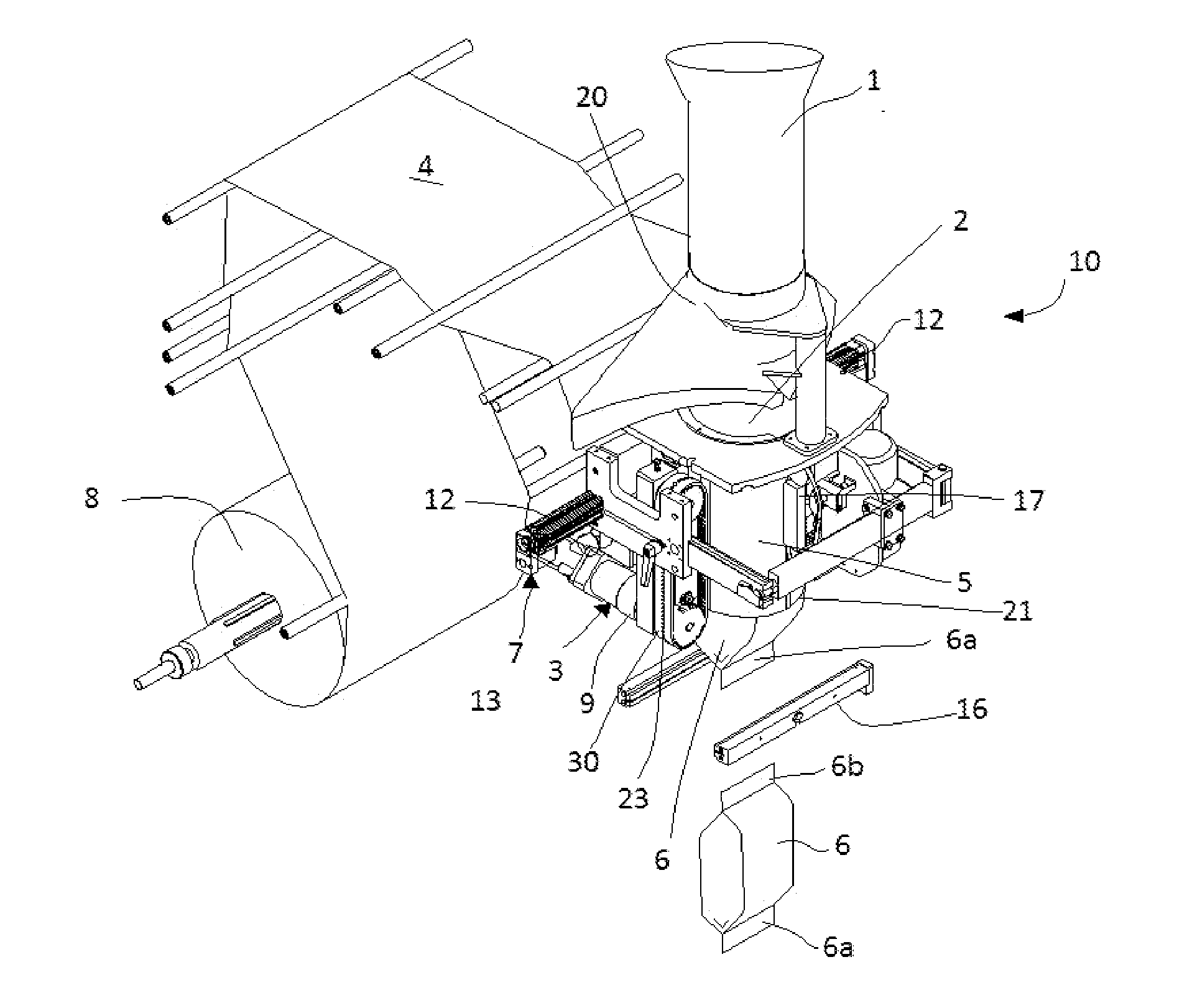
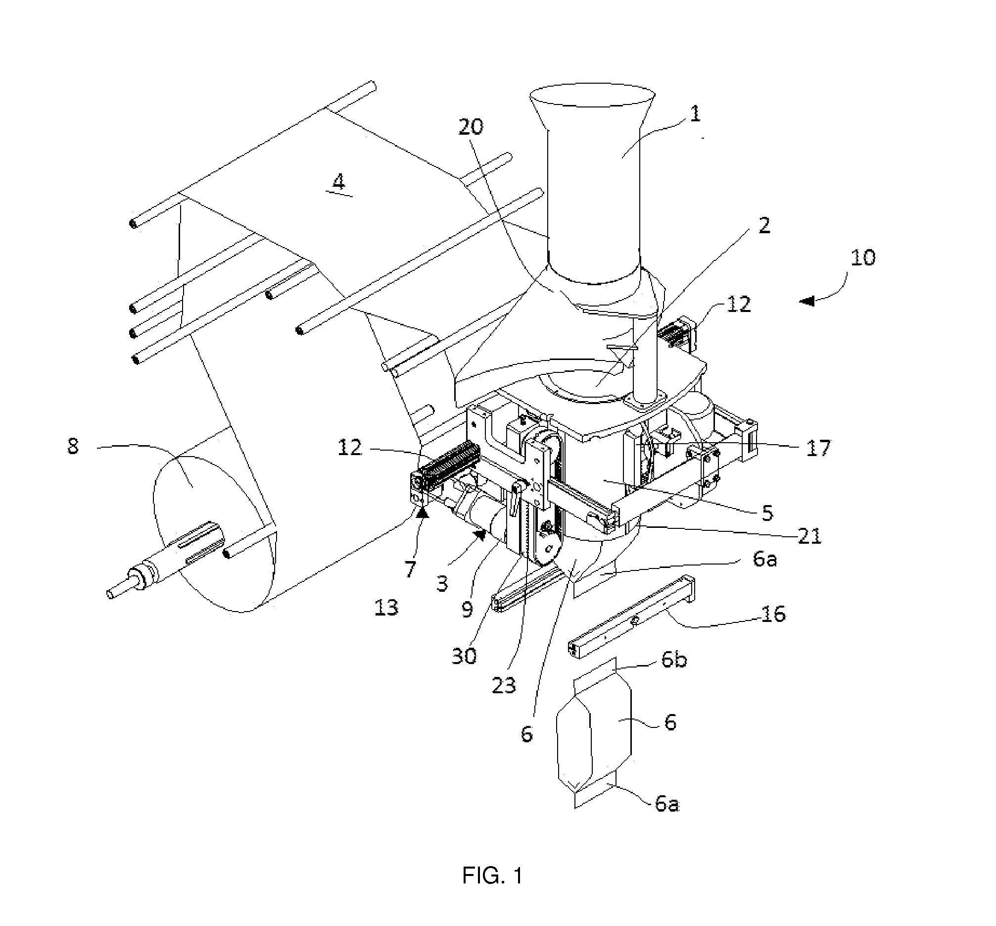
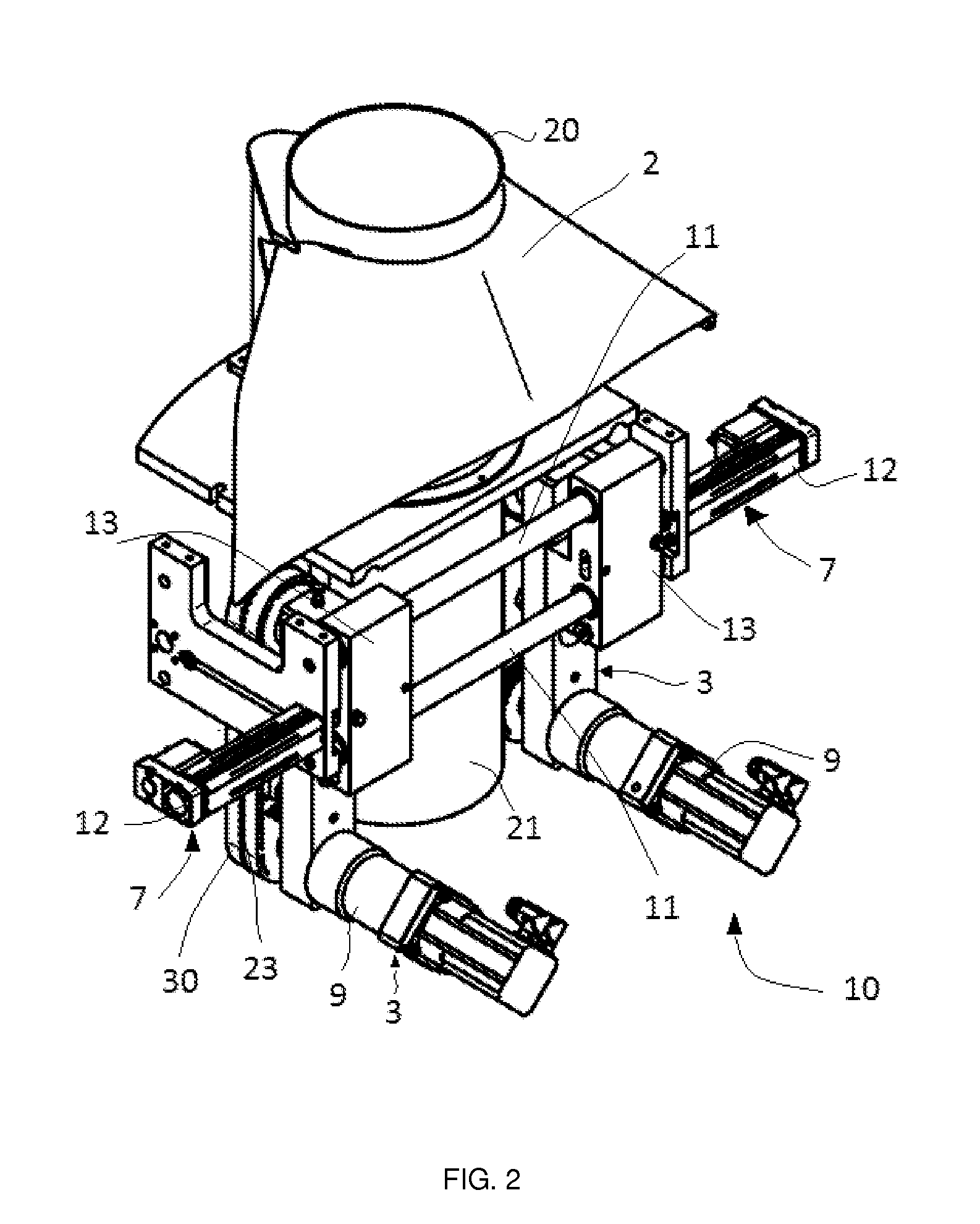
[0043]In a first embodiment, when the control means detects slippage it operates the corresponding displacement module 7 so that the advance module 3 moves towards the forming tool 2. To determine the slippage between a drive belt 30 and the laminar tube 5 the advance of the laminar tube 5 is measured and the advance of the drive belt 30 is measured and the two values are compared. It is determined that there is slippage if they are different values or if the difference between the two values measured is greater than a predetermined relative advance value.
[0044]In such an embodiment the detection means may comprise probes, optical sensors or other detection members capable of detecting the movement of the laminar tube 5 or the movement of the laminar film 4. In the event that the optical sensor is used, the laminar tube 5 or the laminar film 4 may comprise a plurality of marks distributed uniformly and longitudinally, which are detected by the optical sensor.
[0045]This control stage...
second embodiment
[0046]In a second embodiment the control means detects the risk of slippage by measuring the distance of the respective advance module 3 or the respective drive belt 30 in relation to the zero position of the forming tool 2, and comparing said distance with a predetermined distance. The predetermined distance is optimised to drive and move without slippage the laminar tube 5, without there being excessive pressure that leads to higher consumption of energy in the case of vertical friction-type machines, a risk of the laminar tube 5 sticking to the forming tool in vacuum-type machines, or excessive wear of the belt 30 both in friction-type machines and in vacuum-type machines with elements added to the laminar tube 5 or the laminar film 4.
[0047]In this second embodiment, it is determined that there is a risk of slippage if the distance measured does not coincide substantially with the predetermined distance. In this case, the control means operate the displacement module 7 of the cor...
fourth embodiment
[0049]In a fourth embodiment the packaging operation comprises a vacuum operation during which the vacuum is induced by means of the vacuum pump on the laminar tube 5 so that each belt 30 holds and drives the laminar tube 5. In the control operation, the risk of slippage of the corresponding belt 30 and the laminar tube 5 is detected automatically, the vacuum level being measured and it being determined that there is a risk of slippage if the vacuum level measured is smaller than a predetermined threshold vacuum level, the predetermined threshold vacuum level being that which optimally allows the movement of the laminar tube 5 in relation to each belt 30 without there being an excess of power consumption.
[0050]The detection means may comprise a vacuum switch (not shown in the figures), which is adapted to determine the vacuum level provided by the vacuum pump, the vacuum switch being connected to the control means. These types of elements are conventional, and what they actually do ...
PUM
| Property | Measurement | Unit |
|---|---|---|
| distance | aaaaa | aaaaa |
| distance measurement | aaaaa | aaaaa |
| force | aaaaa | aaaaa |
Abstract
Description
Claims
Application Information
 - R&D
- Intellectual Property
- Life Sciences
- Materials
- Tech Scout
- Unparalleled Data Quality
- Higher Quality Content
- 60% Fewer Hallucinations
Browse by: Latest US Patents, China's latest patents, Technical Efficacy Thesaurus, Application Domain, Technology Topic, Popular Technical Reports.
© 2025 PatSnap. All rights reserved.Legal|Privacy policy|Modern Slavery Act Transparency Statement|Sitemap|About US| Contact US: help@patsnap.com