Variable cut off in a double cut folder

Active Publication Date: 2013-11-07
MANROLAND GOSS WEB SYST AMERICAS LLC
View PDF5 Cites 5 Cited by
  • Summary
  • Abstract
  • Description
  • Claims
  • Application Information

AI Technical Summary

Benefits of technology

The patent describes the ability for printers to create products with different cut lengths. Most cutter or former folders are single cut, so changing the length of the cut requires changing the speed of the cutting cylinders or replacing them with another that has a different circumference. To achieve optimal speed and accuracy, some printers use electronic cam profiles to speed up or slow down the cylinders before the knife is in contact with the paper. However, this can result in slower than desired web speeds due to the high inertia of the cutting cylinders and limitations in sampling frequency. The technical effect of the patent is to provide faster and more efficient ways to change the length of cups and other products without slowing down the overall production process.

Problems solved by technology

However, the speed of the knife blades on the cutting cylinder may cause performance issues and product damage.
Thus, it is not possible to increase or decrease the rotational speed of the first cut cylinders to change the cut length.
Doing so would cause product damage due to the relative speeds of the knife to the paper.

Method used


Image

  • Variable cut off in a double cut folder
  • Variable cut off in a double cut folder
  • Variable cut off in a double cut folder

Examples


Embodiment Construction

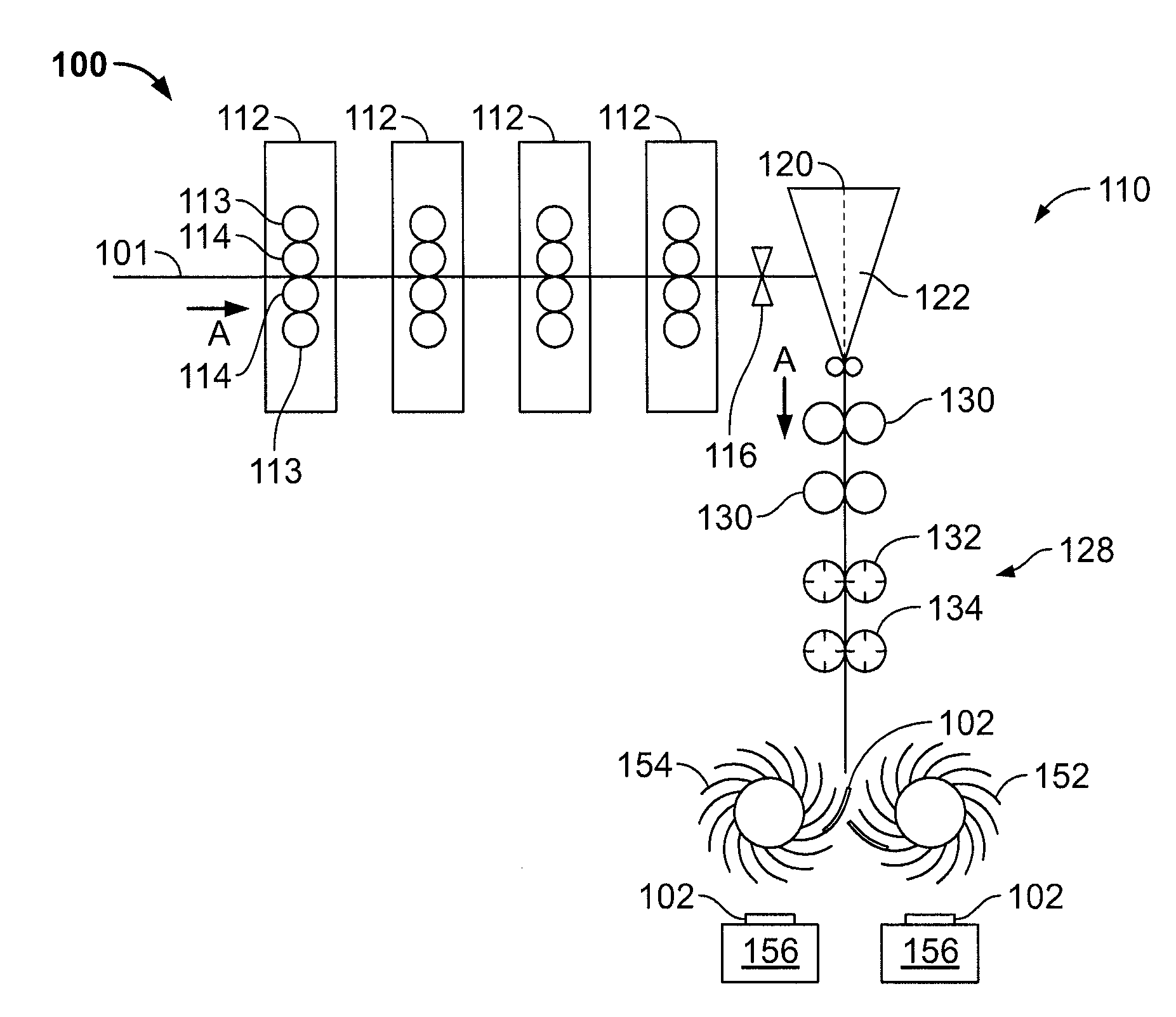
[0036]For a single cut folder, the signature creation is often limited by snap back and pushing the lead edge of the paper into machine tapes. Snap back causes the signature to become non-planar and can produce skew in the cut edge. A common method to reduce snap back is through the use of a final nipping point as close to the entrance of the cutting cylinders as possible. A second limitation is pushing the lead edge of the paper into machine tapes, which are used to transport signatures to downstream operations. In order to maximize performance with a single cut folder, the entrance to the machine tapes is located as close to the cutting cylinders as possible. One of the ways to minimize the distance between the cutting cylinder and the tape entrance or the cutting cylinder and the final nip point is by minimizing the diameters of the cutting cylinders. It is common for a nominal cutting cylinder circumference to be 610 mm for a 1220 mm blanket cylinder circumference.

[0037]One of t...


PUM

PropertyMeasurementUnit
Lengthaaaaaaaaaa
Circumferenceaaaaaaaaaa

Abstract

A double cut folder is provided for a printing press. The folder has a first cutting cylinder pair including a first knife cylinder and a first anvil cylinder for perforating a web, and a second cutting cylinder pair including a second knife cylinder and a second anvil cylinder for cutting the web into signatures. Each cutting cylinder pair includes a plurality of knife mounting locations and a plurality of cutting rubber locations. Each knife mounting location is configured to hold a knife box. A first subset of the plurality of knife mounting locations each have a knife box secured therein, and a second subset of the plurality of knife mounting locations do not have a knife box secured therein.

Description

[0001]This application claims priority to U.S. Provisional Application Ser. No. 61 / 641,036, filed May 1, 2012, the entire disclosure of which is hereby incorporated by reference.CROSS-REFERENCE TO RELATED APPLICATIONS[0002]This application contains subject matter related to commonly owned U.S. application Ser. No. 13 / 862,807, filed Apr. 15, 2013, the entire disclosure of which is hereby incorporated by reference.FIELD OF THE INVENTION[0003]The present invention relates generally to printing press equipment and more particularly to cutting devices and cutting folders.BACKGROUND[0004]U.S. Pat. No. 5,865,082, hereby incorporated by reference herein, discloses a first conveyor assembly and a second conveyor assembly. Cooperating cutting cylinders having a knife and an anvil are integrated into paths of the conveying elements of the first and second conveyor assemblies, seizing a web of material prior to a cutting operation.[0005]U.S. Pat. No. 6,684,746, hereby incorporated by reference ...

Claims


Application Information

Patent Timeline
IPC IPC(8): B26D1/40
CPCB26D1/405B26D7/26B26D9/00B26F1/08B26F1/20B41F13/60Y10T29/49716Y10T83/4838B26D7/2614
Inventor DOUILLARD, GERALD ROGERSPOSATO, JR., JOHN JAMESPOLLOCK, DAVID CLARKEEBERT, DIETER THEODOR
Owner MANROLAND GOSS WEB SYST AMERICAS LLC
Why Eureka
Try Eureka