
Turboprop-powered aircraft

a turboprop aircraft and thermal management technology, applied in indirect heat exchangers, regenerative heat exchangers, lighting and heating apparatus, etc., can solve the problems of correspondingly complex and expensive (in terms of money or power consumption), and achieve simple system solutions, improve surveillance functions, and optimise/maximimise fuel economy. effect of each mission

Inactive Publication Date: 2013-11-07
BAE SYSTEMS PLC
View PDF7 Cites 15 Cited by
  • Summary
  • Abstract
  • Description
  • Claims
  • Application Information

AI Technical Summary

Benefits of technology

The present invention provides a way to capture heat from a turboprop-powered aircraft's engine to heat the pay load without taking heat from the engine used for propulsion. This helps to extend the aircraft's flight endurance. Additionally, the invention allows the aircraft to fly at higher altitudes with slower speeds, which is useful for surveillance purposes. This invention reduces the power and air offtake demands on the engine, making it simpler and more flexible to maintain the necessary thermal environment for reliable and effective operation of the aircraft's equipment without additional fuel consumption or power-offtake penalties. It also allows for the aircraft to carry more fuel and extend the duration of the mission.

Problems solved by technology

On the other hand, many other types of aircraft and / or aircraft mission profiles have highly demanding thermal management requirements, but factors such as the cost and complexity of those aircraft, and / or the high availability of fuel driven power during flight, make providing correspondingly complex and expensive (in terms of money or power consumption) thermal management arrangements practicable.

Method used


Image

  • Turboprop-powered aircraft
  • Turboprop-powered aircraft
  • Turboprop-powered aircraft

Examples


Embodiment Construction

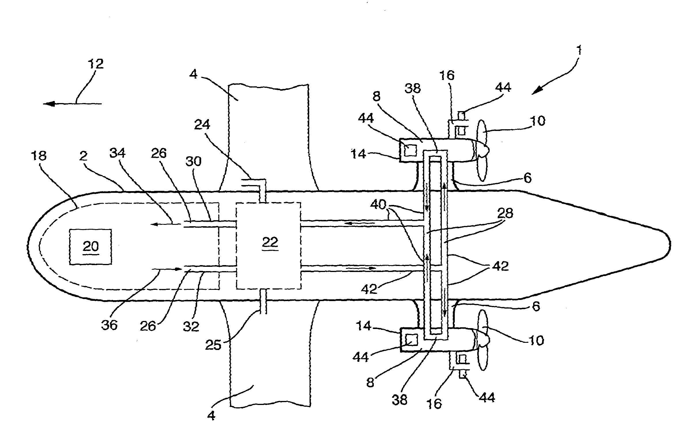
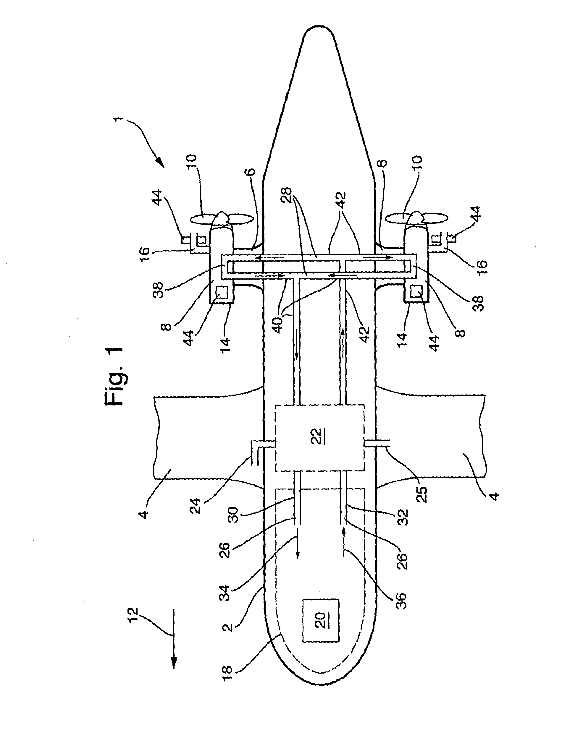
[0040]FIG. 1 is a schematic illustration (not to scale) of a turboprop-powered MALE aircraft 1 comprising a first embodiment of a thermal management system.

[0041]The turboprop-powered MALE aircraft 1 comprises a fuselage 2, wings 4 and engine support pylons 6.

[0042]Gas turbine engines 8, coupled to propellers 10, are attached to the engine support pylons 6. The gas turbine engines 8 drive the propellers 10 to provide propulsion to make the turboprop-powered MALE aircraft 1 travel in a flight direction 12. Each gas turbine engine 8 is encased in an engine casing 14, which itself is encased in a nacelle (not shown). Each gas turbine engine 8 has one or more exhaust ducts 16 (for clarity, in FIG. 1 only one exhaust duct 16 is shown for each gas turbine engine 8).

[0043]The turboprop-powered MALE aircraft 1 further comprises an equipment bay 18, which will typically carry a payload 20. The payload 20 may comprise one or more of surveillance equipment, navigation equipment, communications...


PUM


Abstract

A method and apparatus are disclosed for a turboprop-powered medium altitude long endurance (MALE) aircraft, having: a heat exchanger with a heat-storage material, for example a heat-storage wax; and an air recirculation path. The heat exchanger can be arranged to cool air recirculating around the air recirculation path which is arranged to provide cooling to the MALE aircraft, for example to an equipment bay. The heat-storage material may be cooled by ground-based cooling apparatus when the aircraft is on the ground and / or by ram air when the aircraft is in flight. The heat-storage material may have a melting point selected so as to be rendered solid during ground-based cooling and / or ram air cooling, and / or selected so as to undergo melting whilst cooling the air recirculating around the air recirculation path.

Description

FIELD OF THE INVENTION[0001]The present invention relates to thermal management of a turboprop aircraft, in particular a turboprop-powered Medium Altitude Long Endurance (MALE) aircraft.BACKGROUND[0002]For aircraft in general, many types of thermal management arrangements are known.[0003]On the one hand, many types of aircraft and / or aircraft mission profiles are relatively simple, for example light aircraft with piston-powered propellers flying at low speeds at low altitude, and the thermal management arrangements may accordingly be relatively undemanding, e.g. use of simple ram air may suffice.[0004]On the other hand, many other types of aircraft and / or aircraft mission profiles have highly demanding thermal management requirements, but factors such as the cost and complexity of those aircraft, and / or the high availability of fuel driven power during flight, make providing correspondingly complex and expensive (in terms of money or power consumption) thermal management arrangement...

Claims


Application Information

Patent Timeline
Patent Type & Authority Applications(United States)
IPC IPC(8): B64D13/00B64F1/36
CPCB64D13/00B64F1/362B64D13/08B64D2013/0614B64D2013/0633B64D15/02Y02T50/50B64D13/06
Inventor SMITH, STEPHEN JOHN RICHARDWATT, KIERAN JAMESS
Owner BAE SYSTEMS PLC
Learn More