Apparatus and method for calibrating a radio positioning based position finding device

a position finding and positioning system technology, applied in wave based measurement systems, instruments, reradiation, etc., can solve the problems of inability to achieve the desired average level of accuracy, inability to provide blanket coverage of infrared and rfid systems, and inability to achieve ideal free-field conditions

Active Publication Date: 2013-10-31
FRAUNHOFER GESELLSCHAFT ZUR FOERDERUNG DER ANGEWANDTEN FORSCHUNG EV
View PDF4 Cites 4 Cited by
  • Summary
  • Abstract
  • Description
  • Claims
  • Application Information

AI Technical Summary

Benefits of technology

[0021]According to an embodiment, an apparatus for calibrating a position finding device may have: a means for comparing a received radio signal pattern to a multitude of reference radio signal patterns, said means being configured to select a selection subset from the multitude of reference radio signal patterns by means of a measure of matching between the received radio signal pattern and one reference radio signal pattern, respectively, from the multitude of reference radio signal patterns; characterized in further comprising a means for determining signal strength difference pattern between the received radio signal pattern and one reference radio signal pattern, respectively, of the selection subset; and a means for determining a calibration offset based on the signal strength difference pattern and for providing the calibration offset to the position finding device for using the calibration offset to accordingly correct signal strengths determined by it, the received radio signal pattern includes at least one of transmitter IDs of receivable radio transmitters and signal strengths of received radio signals, and wherein the means for comparing is further configured to relate relative signal strengths for different transmitter IDs within the received radio signal pattern to corresponding relative signal strengths within the respective one of the multitude of reference radio signal patterns and to infer the measure of matching therefrom.

Problems solved by technology

Presently, however, these technologies do not exhibit the desired average levels of accuracy.
Infrared and RFID systems are generally not available with blanket coverage and are tied to specific preconditions.
However, WLAN signals are strongly screened off by buildings and other obstacles; in particular in areas with extensive WLAN coverage, there are usually no ideal free-field conditions, since said areas are located in urban areas.
Thus, it is not directly possible to infer the distance between a mobile terminal and a base station or any other communication partner from the signal strength and / or field strength measured.
This is of interest particularly when the mobile terminal, such as a WLAN-capable device, is held immediately in front of the body of a user, so that the body may cause shadow effects.

Method used


Image

  • Apparatus and method for calibrating a radio positioning based position finding device
  • Apparatus and method for calibrating a radio positioning based position finding device
  • Apparatus and method for calibrating a radio positioning based position finding device

Examples


Embodiment Construction

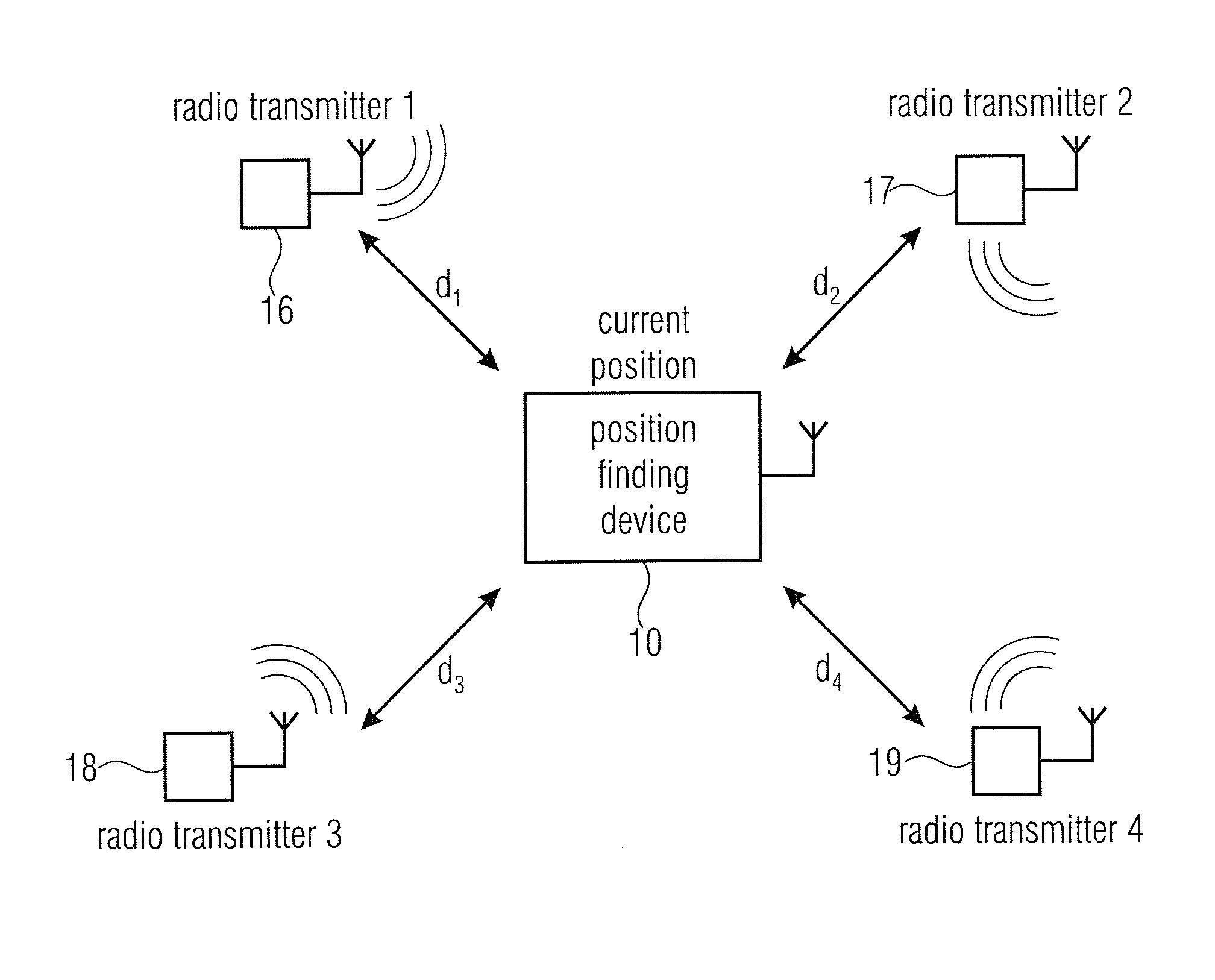
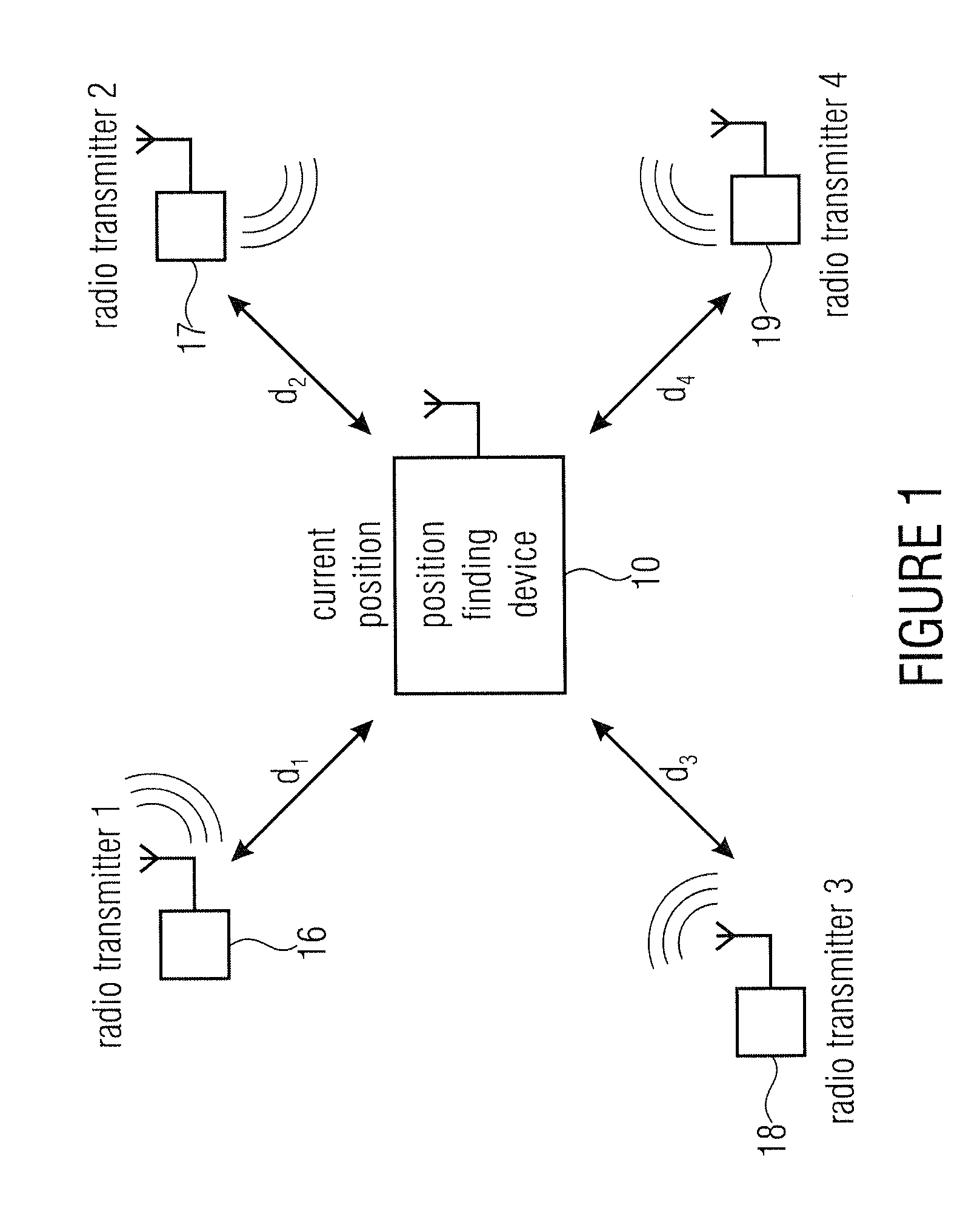
[0059]FIG. 1 is to illustrate the basic principle of radio-based localization. At a given point in time, a position finding device 10 is located at a current position to be found. The position finding device 10 is located within the range of four radio transmitters 16, 17, 18, and 19, so that the position finding device 10 may receive radio signals from the radio transmitters 16 to 19. The distance between the position finding device 10 and the radio transmitters 16 to 19 is d1, d2, d3, and d4, respectively. However, said distances are not known in advance to the position finding device.

[0060]Coarse position finding may be performed already because of the fact that the position finding device 10 is located within the ranges of the radio transmitters 16 to 19. To this end, each of the radio transmitters 16 to 19 marks the radio signals it sends out with a transmitter ID. For more accurate position finding, use may be made of the fact that radio signals weaken as a function of the dis...


PUM


Abstract

Described is an apparatus for calibrating a position finding device, having a comparer for comparing a received radio signal pattern to a multitude of reference radio signal patterns, a determiner for determining a signal strength difference, and a determiner for determining a calibration value. The comparer for comparing is configured to select a selection subset from the multitude of reference radio signal patterns by means of a measure of matching between the received radio signal pattern and one reference radio signal pattern, respectively. Determination of the calibration value is based on the signal strength difference, and the determiner for determining the calibration value is further configured to provide the calibration value to the position finding device. Also described are a position finding device for radio-based localization, having such an apparatus for calibrating, a method of calibrating a position finding device based on radio-based localization, and a computer program for performing the method are described.

Description

CROSS-REFERENCE TO RELATED APPLICATIONS[0001]This application is a continuation of copending International Application No. PCT / EP2011 / 056442, filed Apr. 21, 2011, which is incorporated herein by reference in its entirety, and additionally claims priority from U.S. Application No. 61 / 326,754, filed Apr. 22, 2010 and from European Application No. 10176470.2, filed Sep. 13, 2010, all of which are incorporated herein by reference in their entirety.BACKGROUND OF THE INVENTION[0002]The field of the present invention relates to calibration of a position finding device of a radio-based positioning system, and in particular to calibration with regard to a signal strength of received radio signals.[0003]Different positioning technologies are available for localizing mobile terminals. The probably best-known system for localization and / or navigation in the outdoor domain is the satellite-aided Global Positioning System (GPS). For localization and / or navigation within buildings, or indoors, var...

Claims


Application Information

Patent Timeline
Patent Type & Authority Applications(United States)
IPC IPC(8): G01S5/02
CPCG01S5/021G01S5/0252G01S5/04G01S5/14G01S11/06
Inventor MEYER, STEFFENHUPP, JUERGENVAUPEL, THORSTENHAIMERL, STEPHAN
Owner FRAUNHOFER GESELLSCHAFT ZUR FOERDERUNG DER ANGEWANDTEN FORSCHUNG EV
Why Eureka
Try Eureka