Seat for Spinning Reel

a spinning reel and seat technology, applied in the field of fishing rod handles, can solve the problems of reels that are prone to rocking lock nuts used to secure the reel to the rod may loosen, and suffer from the bending of the reel from side to side, so as to reduce user contact and facilitate gripping surface

Inactive Publication Date: 2013-10-31
G LOOMIS
View PDF9 Cites 13 Cited by
  • Summary
  • Abstract
  • Description
  • Claims
  • Application Information

AI Technical Summary

Benefits of technology

[0011]In various embodiments, a butt portion is provided on a user-proximal end of the handle. Butt portions of the present disclosure provide numerous advantages, including, for example, overall balancing effects for the handle and / or rod and the ability to replace the user-proximal portion of the handle (which may be subject to high impact and / or abuse when the rod is set down). In various embodiments, a butt portion of the present disclosure further comprises internal features, such as a nut portion for receiving additional handle components. In one embodiment, an internal portion of the butt comprises a female threaded or nut portion for receiving a forward portion of the handle. Selective securement of at least these two features provides the ability to compressively secure a reel seat to the handle.
[0014]Various embodiments of the present disclosure provide for an ergonomic grip. An ergonomic grip surface is achieved through, for example, the provision of cork to reduce user-contact with metal surfaces and provide a comfortable gripping surface.

Problems solved by technology

Fishing rods and handles of the prior art suffer from a number of disadvantages, including conventional tubular reel seats where the reel foot does not sit firmly and the reel tends to rock from side to side.
Another common fault with conventional reel seats is that lock nuts used to secure the reel to the rod may loosen due to handling when casting and fishing and must be periodically re-tightened.
Rods and the associated reel and reel seat components are also susceptible to corrosion, primarily due to repeated water exposure, and this may complicate removal and / or application of the reel.
Additionally, known rod and reel systems provide for a significant amount of contact between metal components and a user's hand.
Such contact reduces comfort of the user experience, complicates a user's ability to grip the rod particularly in the presence of moisture, and poses a risk of contact with and loosening of adjustable or rotatable components.
Additional disadvantages of many rod and / or reels include manufacturing and economic disadvantages.
This lengthy and complicated list of seat assembly parts leads to greater expense in production and assembly and also increases the number of components that may be lost or corrode, requiring replacement.
The procedure for assembling the conventional spinning handle is also complex and unduly increases the cost of manufacturing the rod.

Method used


Image

  • Seat for Spinning Reel
  • Seat for Spinning Reel
  • Seat for Spinning Reel

Examples


Embodiment Construction

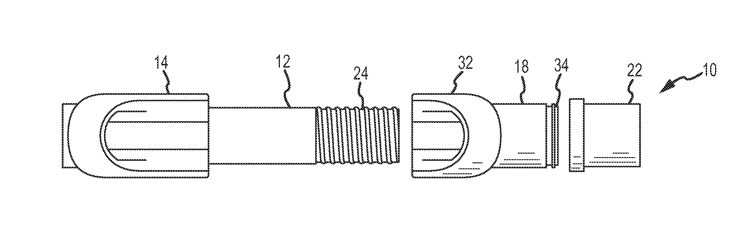
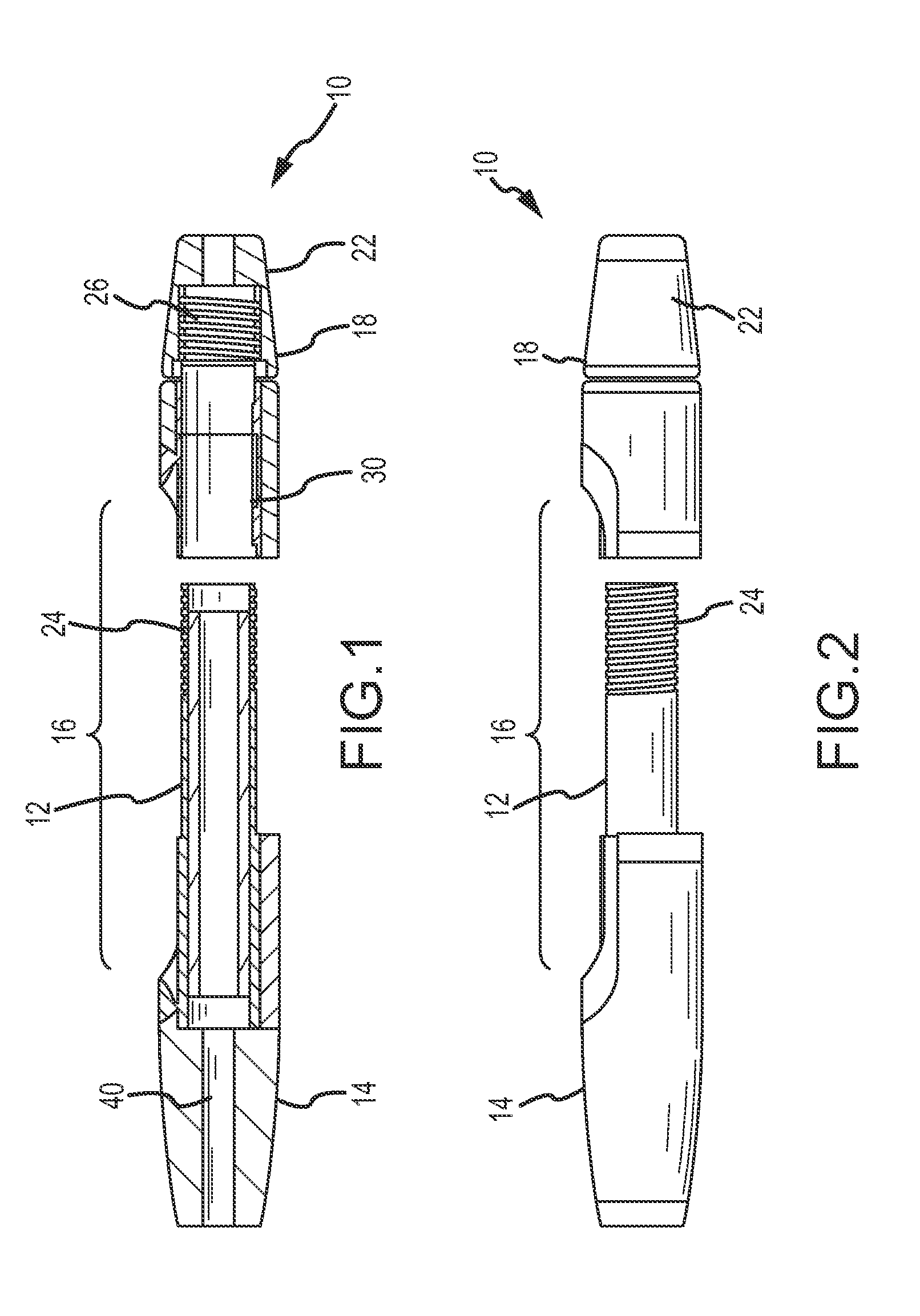
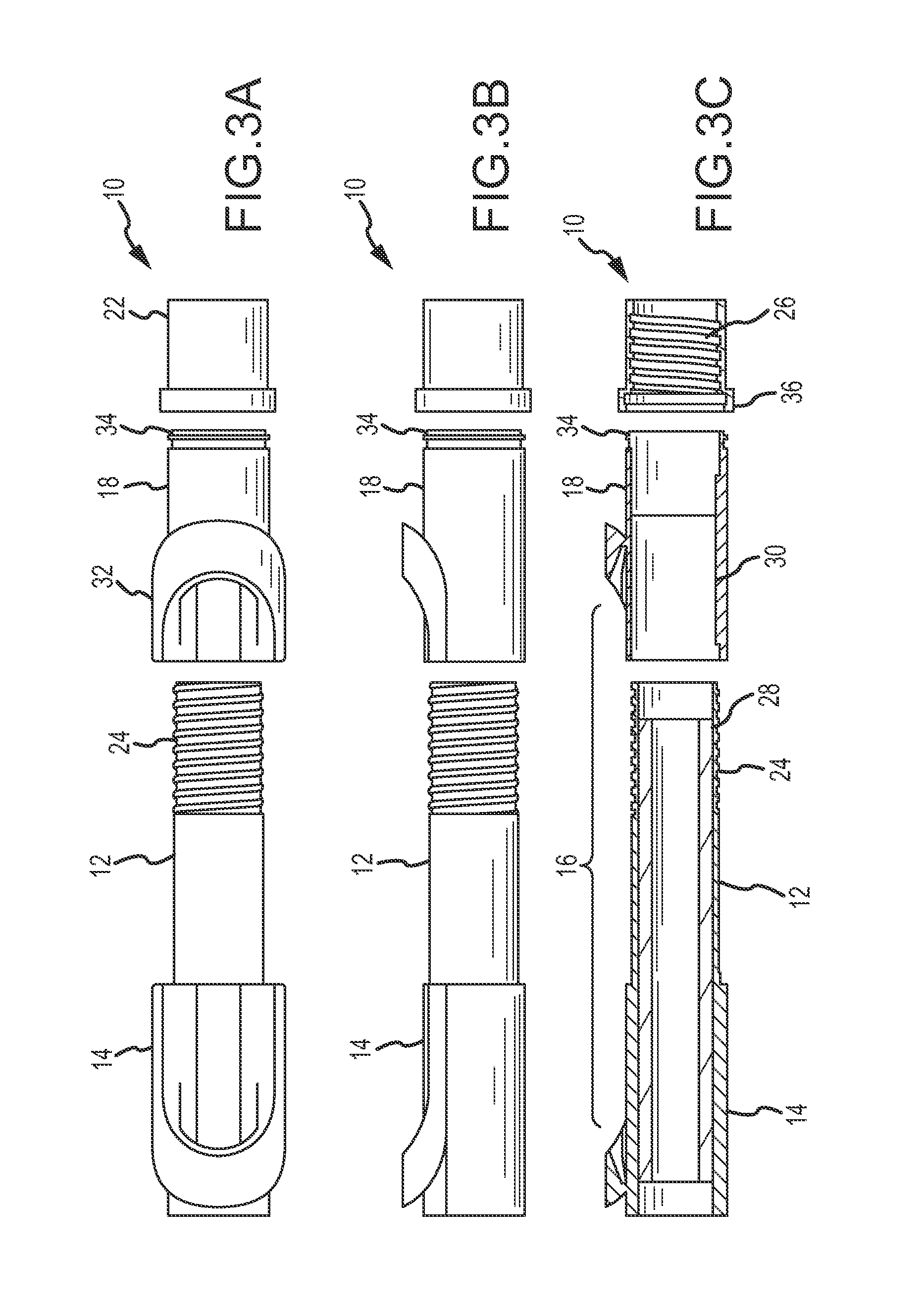
[0029]To acquaint persons skilled in the pertinent arts most closely related to the present invention, a preferred embodiment of the method that illustrates the best mode now contemplated for putting the invention into practice is described herein by, and with reference to, the annexed drawings that form a part of the specification. The exemplary method is described in detail without attempting to describe all of the various forms and modifications in which the invention might be embodied. As such, the embodiments described herein are illustrative, and as will become apparent to those skilled in the arts, can be modified in numerous ways within the scope and spirit of the invention.

[0030]Referring to FIGS. 1-5, a handle portion for a fishing rod according to various embodiments of the present invention is shown. It should be understood that the drawings are not necessarily to scale. In certain instances, details that are not necessary for an understanding of the invention or that re...


PUM


Abstract

A handle for a fishing rod is provided. The handle is of multi-piece construction and comprises a reel seat for securely receiving a fishing reel of various types. Portions of the handle are secured together to selectively form a secure connection between a rod and a reel.

Description

[0001]This Non-Provisional Application claims the benefit of priority from U.S. Provisional Patent Application Ser. No. 61 / 620,789 filed Apr. 5, 2012, the entire disclosure of which is hereby incorporated by reference in its entirety.FIELD OF THE INVENTION[0002]The present invention relates to fishing rods and, more particularly, to a fishing rod handle portion for accommodating reels, including open faced spinning reels and reel feet of various forms.BACKGROUND OF THE INVENTION[0003]Fishing rods are known to comprise a handle portion proximal to a user, the handle portion useful for manipulating the rod as well as securing a fishing reel. Fishing reels are provided in various forms, including spinning reels with a reel foot for contacting the handle portion.[0004]Fishing rods and handles of the prior art suffer from a number of disadvantages, including conventional tubular reel seats where the reel foot does not sit firmly and the reel tends to rock from side to side. Another commo...

Claims


Application Information

Patent Timeline
Patent Type & Authority Applications(United States)
IPC IPC(8): A01K87/06A01K87/08A01K87/00
CPCA01K87/06A01K87/00A01K87/08A01K87/02
Inventor POE, JUSTINBRINKERHOFF, DAVID
Owner G LOOMIS
Why Eureka
Try Eureka