
Electric three-wheel vehicle

a three-wheel vehicle and electric technology, applied in the direction of battery/cell propulsion, cycle equipment, etc., can solve the problem of large left-right width of the power unit, achieve the effect of small size, enhance weight balance, and facilitate starting

Active Publication Date: 2013-10-24
HONDA MOTOR CO LTD
View PDF1 Cites 22 Cited by
  • Summary
  • Abstract
  • Description
  • Claims
  • Application Information

AI Technical Summary

Benefits of technology

The present invention aims to improve the balance of electric vehicles with a power unit between the rear wheels and make the power unit smaller in size.

Problems solved by technology

However, the conventional configuration has a problem that the left-right width of the power unit is large.

Method used


Image

  • Electric three-wheel vehicle
  • Electric three-wheel vehicle
  • Electric three-wheel vehicle

Examples


Embodiment Construction

[0024]Explanations will be hereinbelow provided for an embodiment of the present invention by referring to the drawings. It should be noted that the directions, such as frontward, rearward, leftward and rightward, in the following explanations are the same as the directions in the light of the vehicle to be described below unless otherwise stated therein. In addition, an arrow FR indicating a direction to the front of the vehicle, an arrow LH indicating a direction to the left of the vehicle, and an arrow UP indicating a direction to the top of the vehicle are shown at appropriate places in the drawings used for the following explanations.

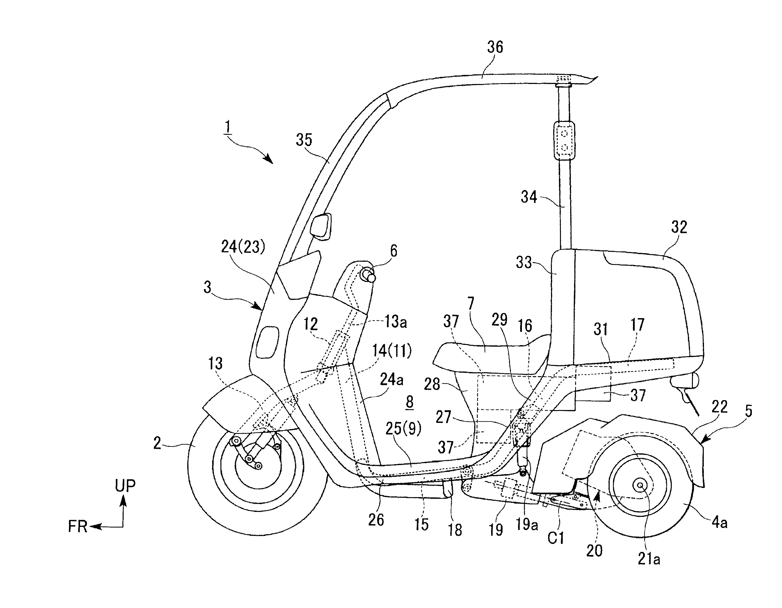
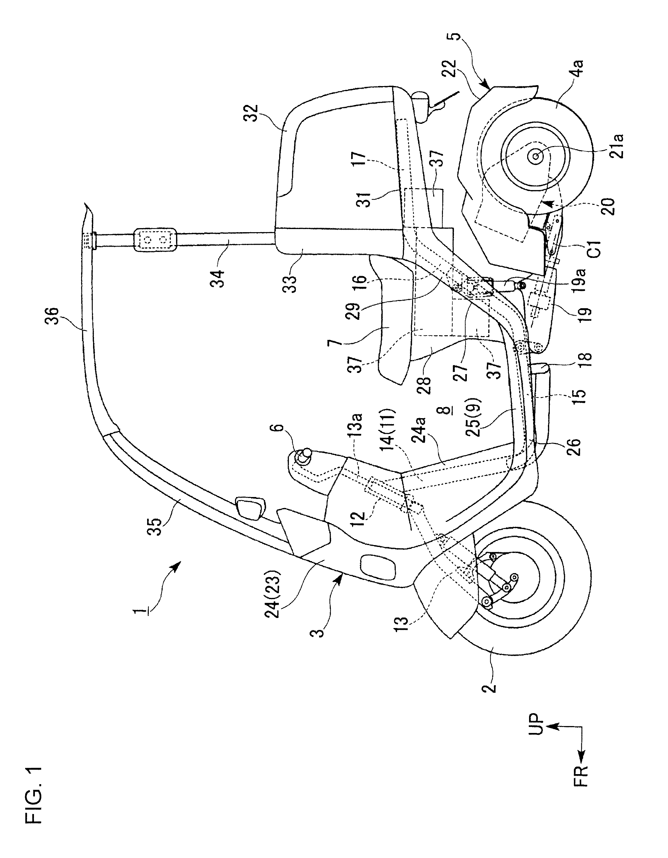
[0025]A motor tricycle 1 shown in FIG. 1 is an example of a swing-type vehicle in which a single front wheel 2, which is a steering wheel, is supported by a front vehicle body 3. Left and right rear wheels 4a, 4b (see FIG. 3), which are two driving wheels, are supported by a rear vehicle body 5. The front vehicle body 3, which can support a rider, ...


PUM


Abstract

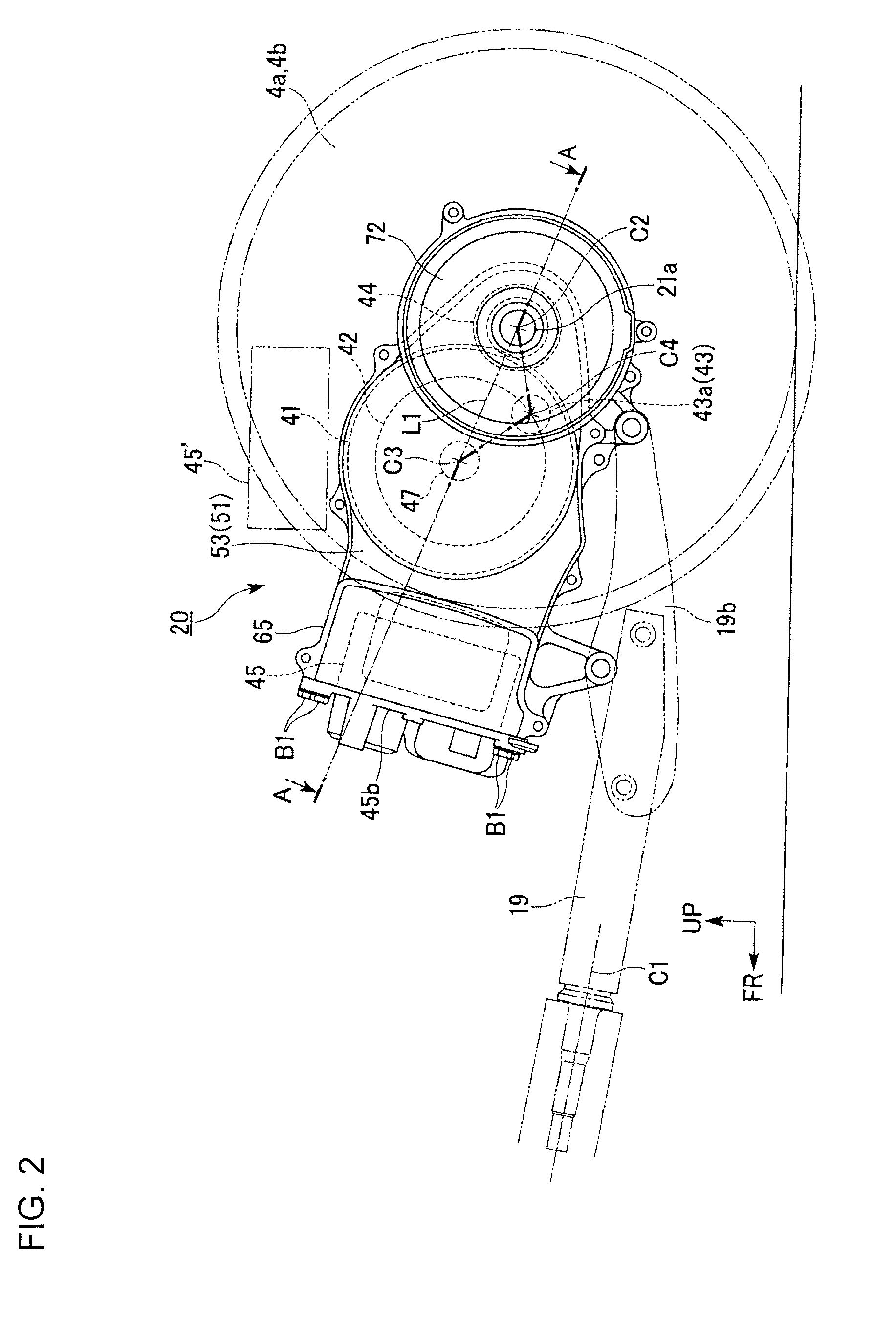
An electric motor and a differential mechanism are placed near a vehicle body left-right center line distributed between the left and right sides of the vehicle body. In addition, at least parts respectively of the electric motor and the differential mechanism are placed on the vehicle body left-right center line. A deceleration mechanism is placed away from the vehicle left-right center line on one of the left and right sides of the vehicle.

Description

BACKGROUND[0001]1. Field[0002]The present invention relates to an electric three-wheel vehicle.[0003]2. Description of Related Art[0004]According to Patent Document 1 (Japanese Patent Publication No. 2011-020558), in an electric three-wheel vehicle, a power unit is placed between the left and right rear wheels (driving wheels). A case of the power unit includes left and right case bodies and a right case cover. An electric motor and a damper mechanism, which connects the electric motor and a transmission (power transmission mechanism), are placed between the left and right case bodies. The transmission and a differential mechanism are placed between the right case body and the right case cover. The electric motor is placed on one of the left and right sides of the vehicle body with respect to the vehicle body left-right center. The damper mechanism is placed at the vehicle body left-right center; and the transmission and the differential mechanism are placed on the other of the left...

Claims


Application Information

Patent Timeline
Patent Type & Authority Applications(United States)
IPC IPC(8): F16H37/08
CPCF16H37/0813B62M7/08B62K2204/00B62J2017/086B62K5/027B62J17/086Y02T10/70B60L50/50
Inventor MIMURA, MASAHIDE
Owner HONDA MOTOR CO LTD
Learn More