
Display device and method for manufacturing the same

a technology for a display device and a manufacturing method, which is applied in the manufacture of electrode systems, electric discharge tubes/lamps, instruments, etc., can solve problems such as light leakage, and achieve the effect of preventing light leakage and suppressing light leakage more effectively

Inactive Publication Date: 2013-10-24
JAPAN DISPLAY INC
View PDF11 Cites 18 Cited by
  • Summary
  • Abstract
  • Description
  • Claims
  • Application Information

AI Technical Summary

Benefits of technology

The present invention provides a display device with a mark that can suppress leakage of light, and a method for manufacturing it. The display device includes a substrate with an image display region, colored layers of plural colors arranged in rows, and a black matrix for preventing light leakage and color mixing between the colored layers. The colored layer is placed in a notch formed by the black matrix, which also acts as a positioning mark. This arrangement effectively suppresses leakage of light compared to a mark made only of a notch. The invention also provides a method for manufacturing the display device by injecting liquid crystal material into an empty cell and sealing the slit in the seal by using the colored layer in the notch as a mark.

Problems solved by technology

However, the black matrix is not formed on an edge portion of a display panel and hence, leakage of light occurs.

Method used


Image

  • Display device and method for manufacturing the same
  • Display device and method for manufacturing the same
  • Display device and method for manufacturing the same

Examples


Embodiment Construction

[0022]Hereinafter, an embodiment of the present invention is explained in conjunction with drawings.

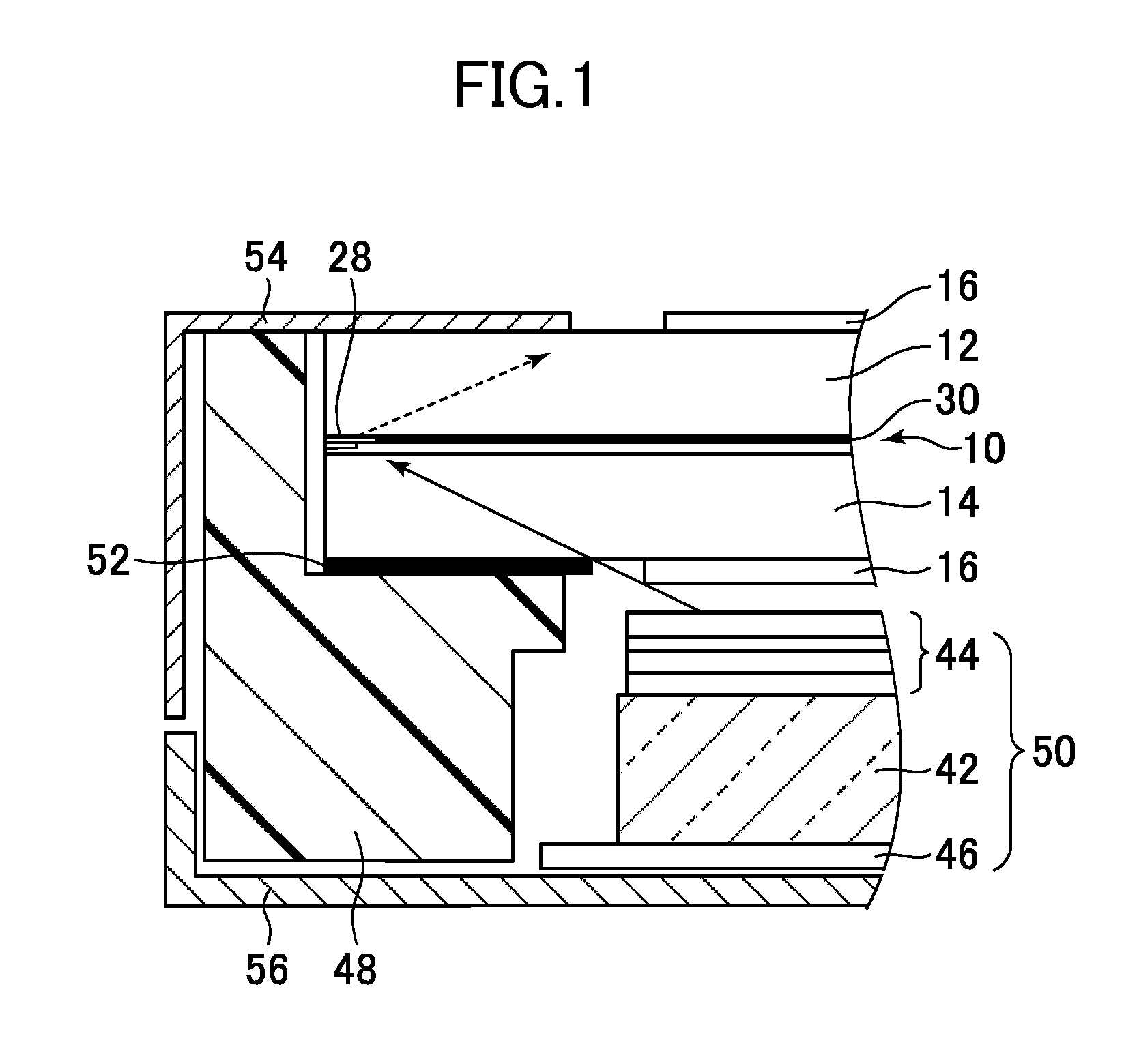
[0023]FIG. 1 is a cross-sectional view of a display device according to the embodiment of the present invention. The display device according to this embodiment is a liquid crystal display device which has a liquid crystal display panel 10. The present invention is, however, also applicable to other display devices such as an organic EL display device having an organic EL (Electro Luminescence) display panel, for example.

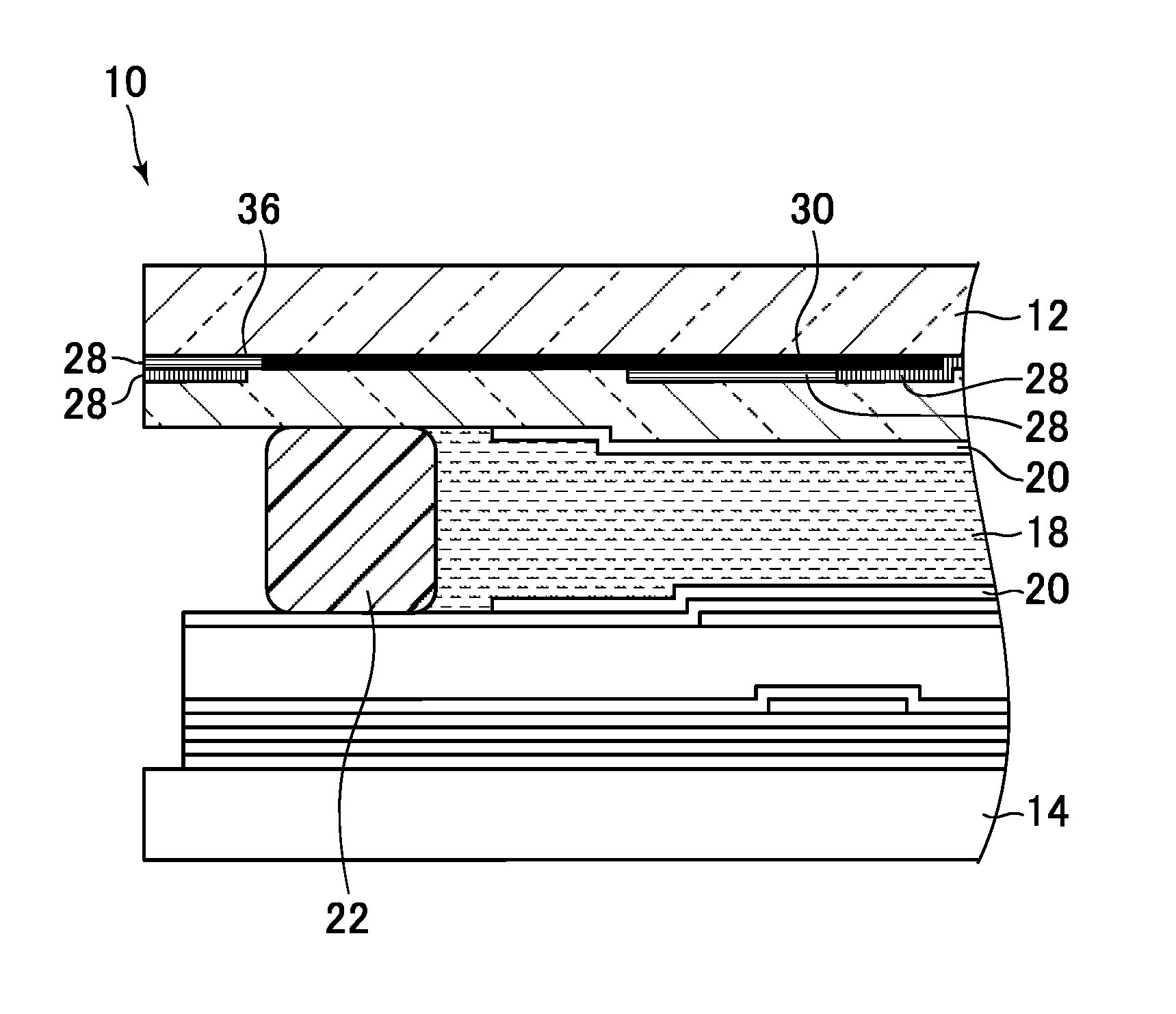
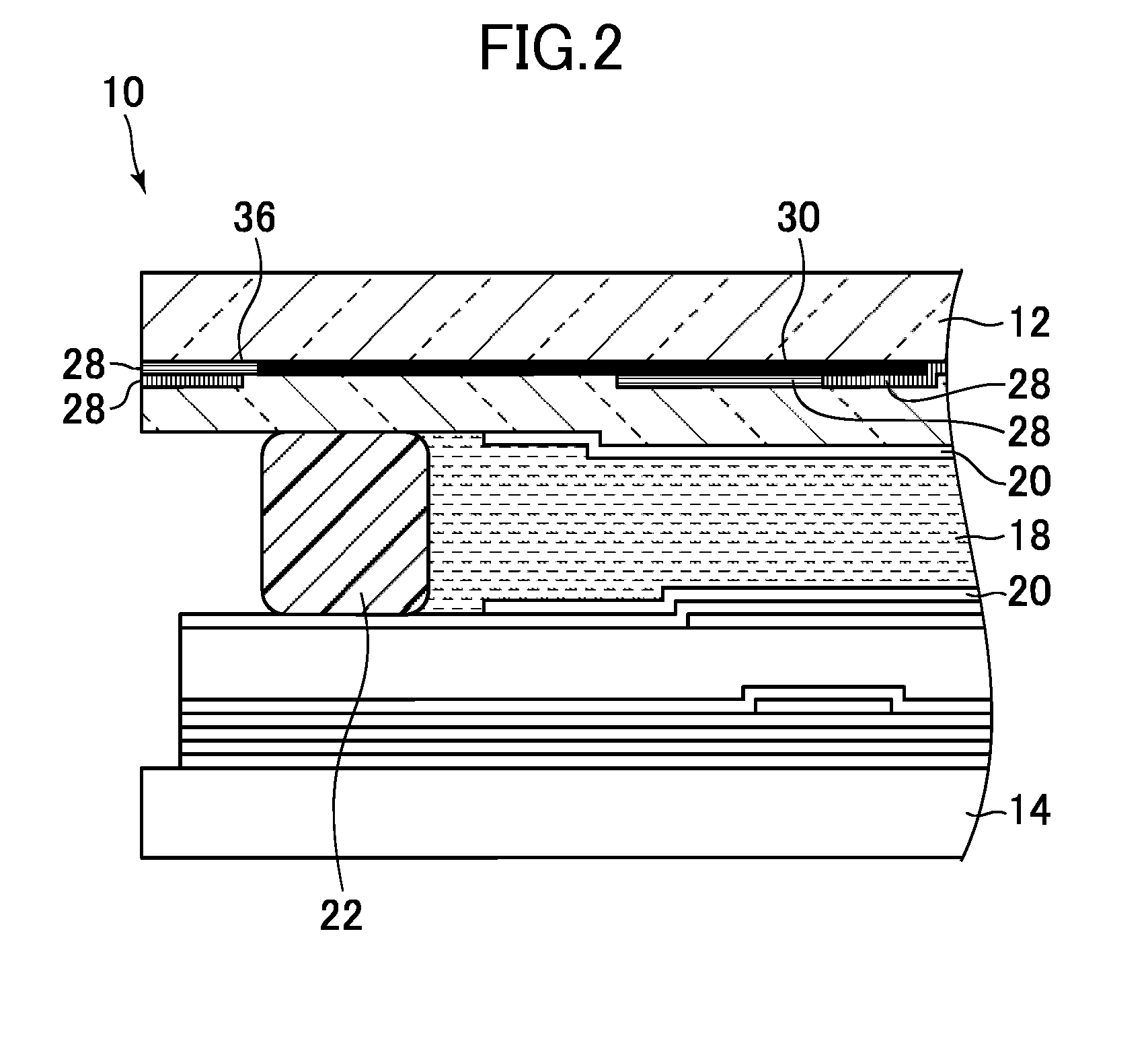
[0024]FIG. 2 is an enlarged cross-sectional view of the liquid crystal display panel 10. FIG. 3 is a plan view of the liquid crystal display panel 10. The liquid crystal display panel 10 is a panel for an image display. The liquid crystal panel includes a first substrate 12 and a second substrate 14 which overlap with each other with a gap formed therebetween. A polarizer 16 shown in FIG. 1 is laminated on a surface of the first substrate 12 and a surface of the secon...


PUM


Abstract

A display device includes: a first substrate which has an image display region; colored layers of plural colors which are arranged in rows on the first substrate and constitute a color filter in the image display region; and a black matrix which is provided for preventing leakage of light as well as color mixing between the colored layers arranged adjacent to each other. The black matrix includes a frame-shaped portion which surrounds the image display region. The frame-shaped portion is formed such that the frame-shaped portion has a notch on an outer side thereof and covers a periphery of the first substrate except for the notch where the frame-shaped portion does not cover the periphery of the first substrate. The colored layer of at least one color is arranged in the notch.

Description

CROSS-REFERENCE TO RELATED APPLICATION[0001]The present application claims priority from Japanese application JP2012-097274 filed on Apr. 23, 2012, the content of which is hereby incorporated by reference into this application.BACKGROUND OF THE INVENTION[0002]1. Field of the Invention[0003]The present invention relates to a display device and a method for manufacturing the display device.[0004]2. Description of the Related Art[0005]A black matrix is formed on a display panel for blocking undesired light. The black matrix is formed while avoiding an edge portion of the display panel so as to make a positioning mark viewable. For example, JP 2008-257014 A discloses a technique where a positioning mark is used for confirming a position where an end-sealing material which closes a liquid crystal injecting opening is provided.[0006]In a display device provided with a backlight, the prevention of leakage of light is important. However, the black matrix is not formed on an edge portion of ...

Claims


Application Information

Patent Timeline
IPC IPC(8): G02F1/1335
CPCG02F1/133512G02F1/133514G02F1/1339
Inventor HASHIMOTO, SATOSHI
Owner JAPAN DISPLAY INC
Learn More