Rotor arrangement and electromechanical transducer having non-parallel permanent magnets

a technology of electromechanical transducer and rotating shaft, which is applied in the direction of dynamo-electric machines, magnetic circuit rotating parts, magnetic circuit shapes/forms/construction, etc., can solve the problems of conventional electromechanical transducer still showing significant axial vibration during operation, electromechanical transducer is not capable of reducing all kinds of vibration occurring during operation in an appropriate manner, etc., to reduce the width of the magnet system, reduce the vibration of the electromechanical transducer, and increase the efficiency of the electromechanical

Inactive Publication Date: 2013-10-24
SIEMENS GAMESA RENEWABLE ENERGY AS
View PDF17 Cites 6 Cited by
  • Summary
  • Abstract
  • Description
  • Claims
  • Application Information

AI Technical Summary

Benefits of technology

The patent text describes a configuration for a transducer that reduces vibration and acoustic noise emission. This is achieved by balancing tangential force components caused by the interaction between the magnets and the stator slotting. The transducer also uses an optimized skew angle to minimize axial vibration and improve efficiency and energy output. These technical effects result in a quieter and more stable operation of the transducer.

Problems solved by technology

However, it has been observed that the conventional electrical machine or conventional electromechanical transducer or conventional rotor arrangement used for an electromechanical transducer is not capable to reduce all kinds of vibration occuring during operation appropriately.
In particular, the conventional electromechanical transducer may still exhibit a significant axial vibration during operation.

Method used


Image

  • Rotor arrangement and electromechanical transducer having non-parallel permanent magnets
  • Rotor arrangement and electromechanical transducer having non-parallel permanent magnets
  • Rotor arrangement and electromechanical transducer having non-parallel permanent magnets

Examples


Embodiment Construction

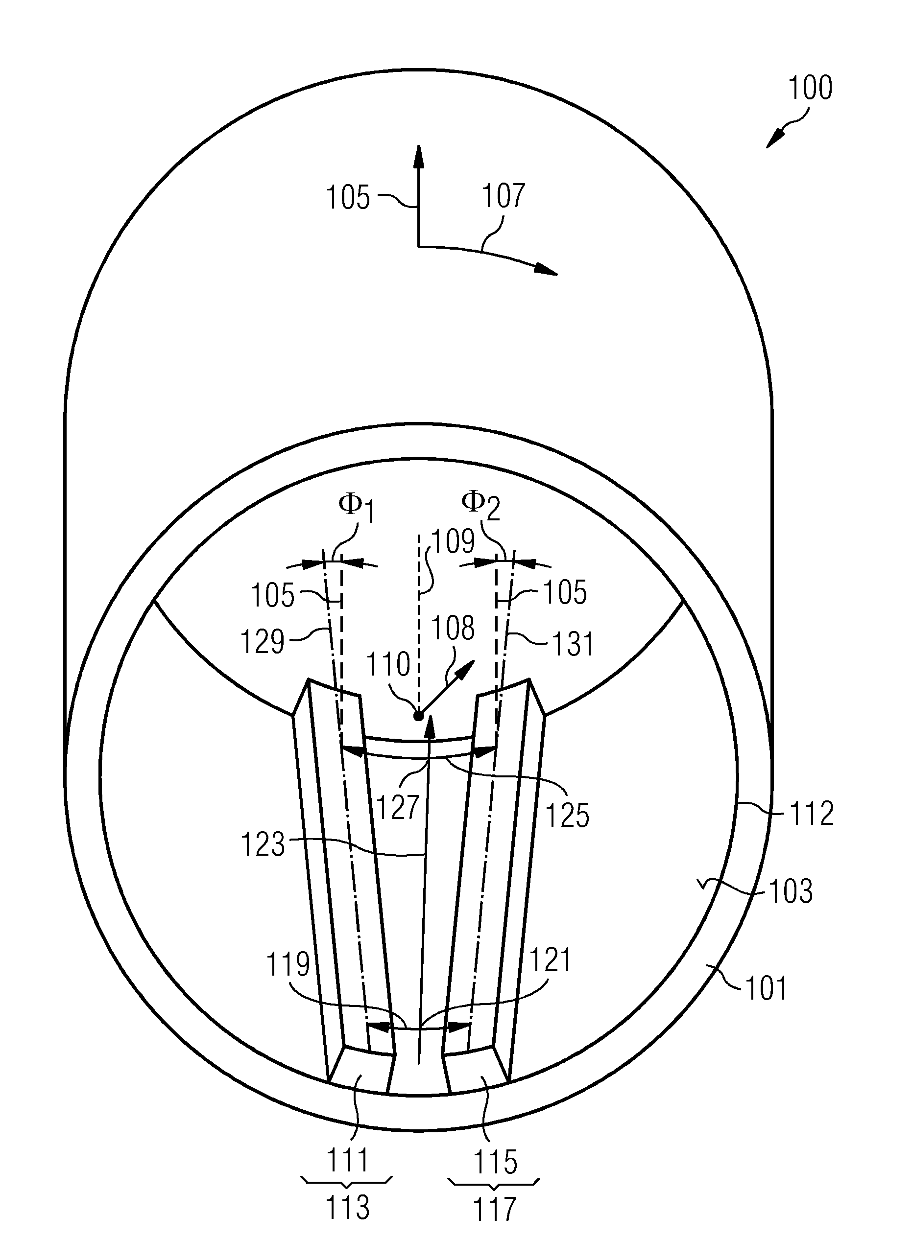
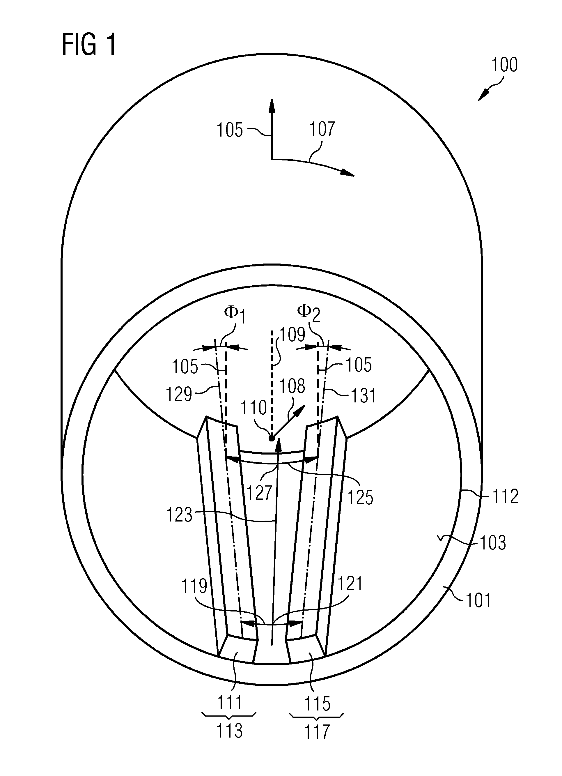
[0061]FIG. 1 illustrates a perspective view of a rotor arrangement 100 according to an embodiment of the present invention. The rotor arrangement 100 comprises a support structure 101, which provides a mounting surface 103 extending in an axial direction 105 and in a circumferential direction 107, wherein the support structure is intended to be rotated around a rotation axis 109 which runs along the axial direction 105. In particular, the support structure 101 is circular in shape and has a cylindrical configuration. The radial direction 108 is indicated in FIG. 1 as pointing from the center 110 of the circle 112 outwards towards the mounting surface 103 of the support structure 101.

[0062]The rotor arrangement 100 comprises a first permanent magnet system 111 which is mounted at the mounting surface 103 at a first circumferential region 113. Further, the rotor arrangement 100 comprises a second permanent magnet system 115 which is arranged at the mounting surface 103 at a second cir...


PUM


Abstract

A rotor arrangement includes a support structure providing a mounting surface extending in an axial direction and a circumferential direction. The support structure is adapted to rotate around the axial direction. A first permanent magnet system is arranged at the mounting surface at a first circumferential region. A second permanent magnet system is arranged at the mounting surface at a second circumferential region. A circumferential distance between the first magnet system and the second magnet system at a first axial position differs from the circumferential distance between the first magnet system and the second magnet system at a second axial position.

Description

CROSS REFERENCE TO RELATED APPLICATIONS [0001]The present application claims priority to European Patent Office application No. 12164938.8 EP filed Apr. 20, 2012, the entire content of which is hereby incorporated herein by reference.FIELD OF INVENTION [0002]The present invention relates to a rotor arrangement and to an electromechanical transducer, in particular a generator, wherein permanent magnets are arranged in a non-parallel manner skewed or inclined relative to an axial direction.BACKGROUND OF INVENTION [0003]An electromechanical transducer, such as an electro motor or a generator converts mechanical energy (in particular rotational energy) into electrical energy or vice versa. Thereby, a stator portion may comprise annularly arranged teeth around which conductors are wound to form plural annularly arranged coils. In particular, the teeth and the coils may be arranged in a cylindrical configuration.[0004]A rotor arrangement may rotate around an axis at the center of the circ...

Claims


Application Information

Patent Timeline
IPC IPC(8): H02K1/27
CPCH02K1/27H02K29/03H02K2201/06Y02E10/72H02K1/2791
Inventor KIMIABEIGI, MOHAMMAD
Owner SIEMENS GAMESA RENEWABLE ENERGY AS
Why Eureka
Try Eureka