Optical connector

Active Publication Date: 2013-10-10
AUTONETWORKS TECH LTD +2
View PDF11 Cites 6 Cited by
  • Summary
  • Abstract
  • Description
  • Claims
  • Application Information

AI Technical Summary

Benefits of technology

The present invention aims to provide an optical connector that is less likely to have its optical output reduced even when a force is applied to the optical fiber in a perpendicular direction. The optical output from the fiber travels in the resin member along the axial direction of the fiber and is focused by the lens before outputting through the resin member to the fiber. The optical path length in the resin member is relatively short, making the optical output less likely to be reduced even if a force is applied to the fiber. The technical effect of the invention is to maintain consistent optical output even under durability testing of the optical connector.

Problems solved by technology

Such problems may be particularly relevant in the above-described conventional technology, because the optical path length of the light passing through the resin member is relatively long as described above.

Method used


Image

  • Optical connector
  • Optical connector
  • Optical connector

Examples


first embodiment

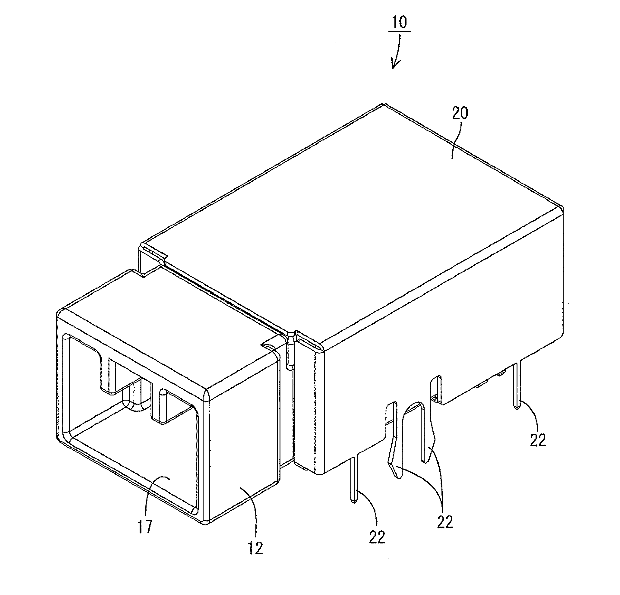
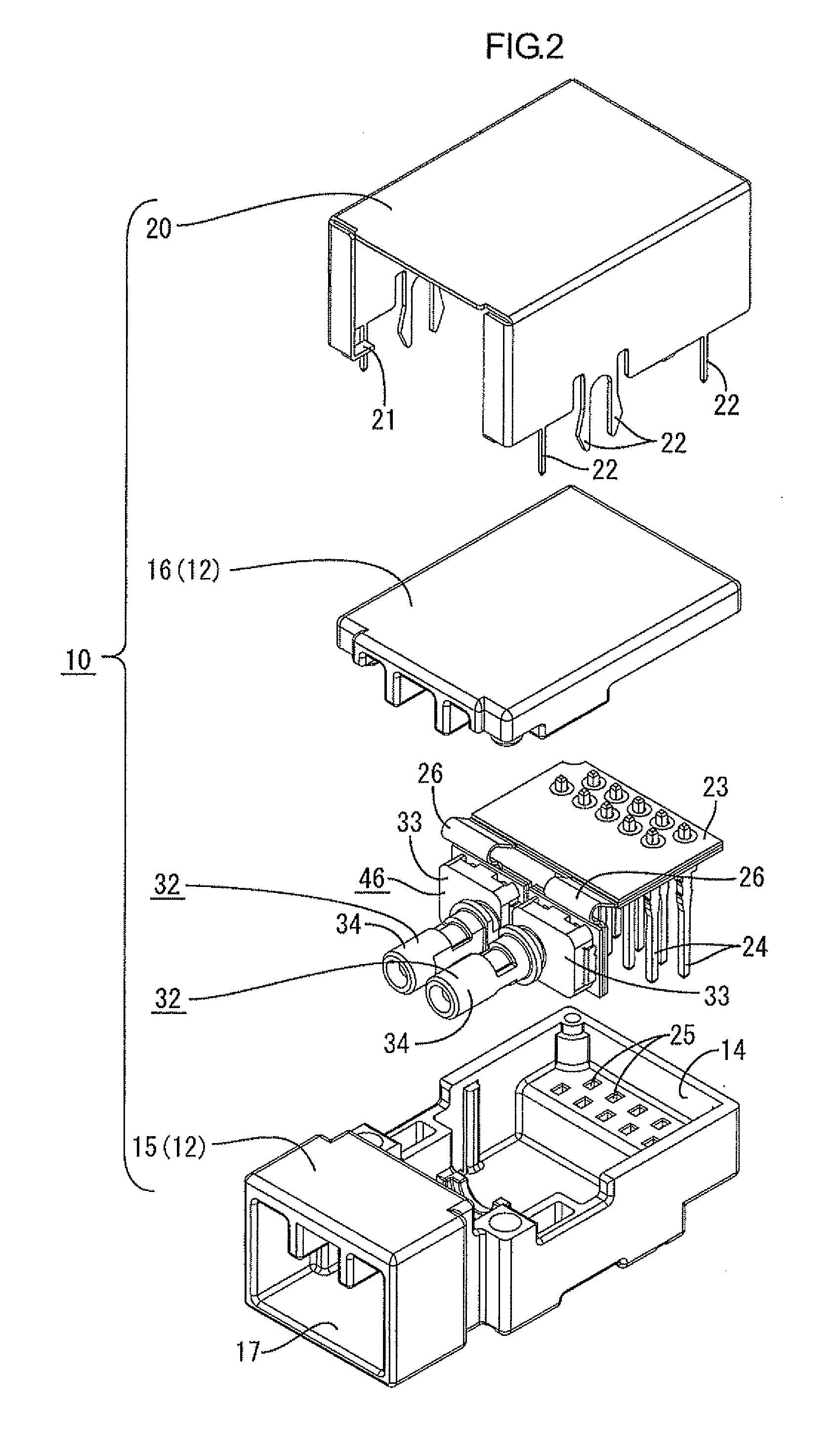
[0059]An embodiment of the present invention will be described with reference to FIG. 1 to FIG. 20. An optical connector 10 according to the present embodiment is attached to an outer board 11 including a conductive path (not illustrated) formed by printed wiring technology. The optical connector 10 includes a housing 12 made of synthetic resin and a photoelectric conversion circuit board 13 housed in the housing 12. An upper side and a lower side referred in the following description correspond to an upper side and a lower side in FIG. 4, respectively. In addition, a front side and a rear side correspond to a left side and a right side in FIG. 4, respectively.

[0060](Housing 12)

[0061]As illustrated in FIG. 4, the housing 12 includes a housing body 15 and a cap 16. The housing body 15 has an opening 14 at its upper side and the cap 16 is fitted to the housing body 15 to close the opening 14. The housing body 15 includes a hood 17 opening to a front side (the left side in FIG. 4). To ...


PUM


Abstract

An optical connector includes a housing, a photoelectric conversion circuit board on which a photoelectric conversion element is mounted, and a resin member made of a light transmissive synthetic resin and arranged on a plate surface of the photoelectric conversion circuit board so as to cover the photoelectric conversion element. The photoelectric conversion circuit board is housed in the housing. The resin member includes a sleeve to which a ferrule attached to an end of an optical fiber is fitted. The sleeve of the resin member is arranged such that an axial direction thereof is substantially perpendicular to the plate surface of the photoelectric circuit board. The resin member integrally includes a lens on an axial line of the sleeve such that the lens faces the photoelectric conversion element.

Description

TECHNICAL FIELD[0001]The present invention relates to an optical connector.BACKGROUND ART[0002]An optical connector described in Patent Document 1 is known as an optical connector configured to optically connect an optical fiber and a photoelectric conversion element. The optical connector includes a housing and an optical module housed in the housing.[0003]The optical module is made of light transmissive synthetic resin and includes a resin member (a holder) to which a ferrule attached to an end of the optical fiber is attached. The resin member includes a tubular sleeve into which the ferrule is fitted. Further, a photoelectric conversion element is provided on a photoelectric element attachment portion of the resin member. The resin member integrally includes a lens on an optical path extending between the optical fiber and the photoelectric conversion element.[0004]The photoelectric conversion element is attached to the photoelectric element attachment portion so as to be positi...

Claims


Application Information

Patent Timeline
IPC IPC(8): G02B6/42H01S5/02315
CPCG02B6/42H01S5/02208H01S5/02236H01S5/183G02B6/4292G02B6/4246G02B6/4265G02B6/4281G02B6/4284G02B6/3897H01S5/023H01S5/0233H01S5/0235H01S5/02315
Inventor KATO, KIYOSHISANO, TOMOMINAKURA, YUJI
Owner AUTONETWORKS TECH LTD
Why Eureka
Try Eureka