
Dot-sight device with polarizers

a technology of polarizers and dot sights, applied in the direction of sighting devices, weapons, weapon components, etc., can solve the problems of difficult to align the line of sight, difficult to do quick aiming, and complicated process of aimed-shot methods, so as to reduce the parallax of the reflection mirror

Inactive Publication Date: 2013-10-10
JUNG IN
View PDF4 Cites 18 Cited by
  • Summary
  • Abstract
  • Description
  • Claims
  • Application Information

AI Technical Summary

Benefits of technology

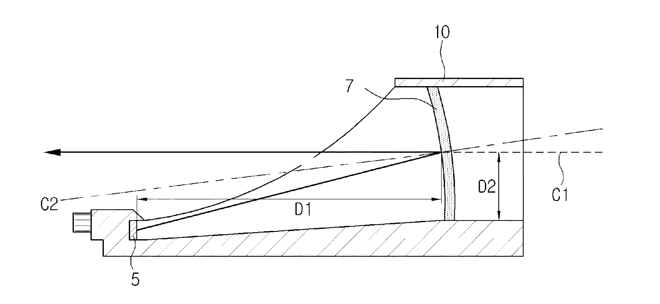
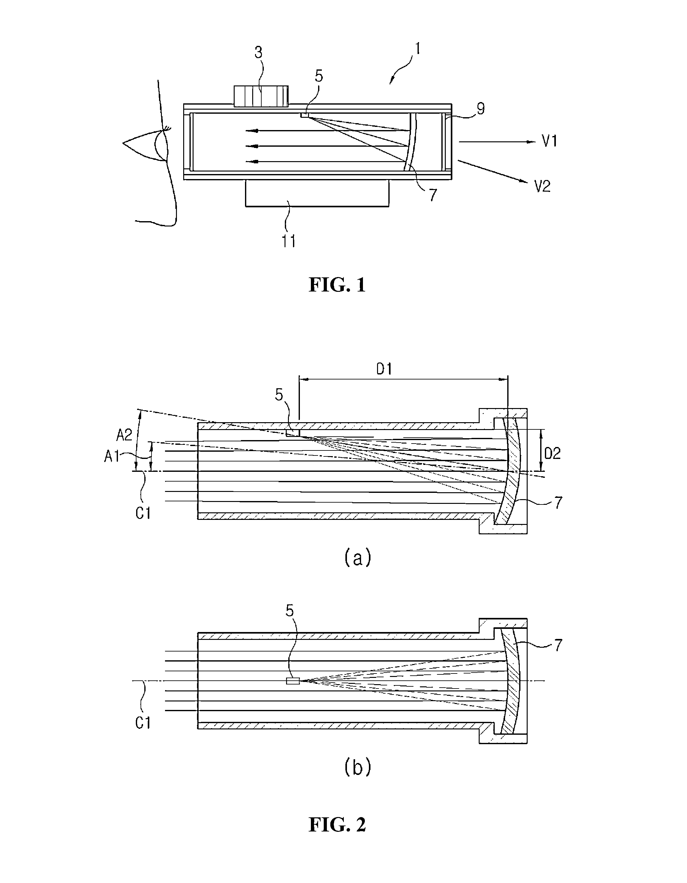
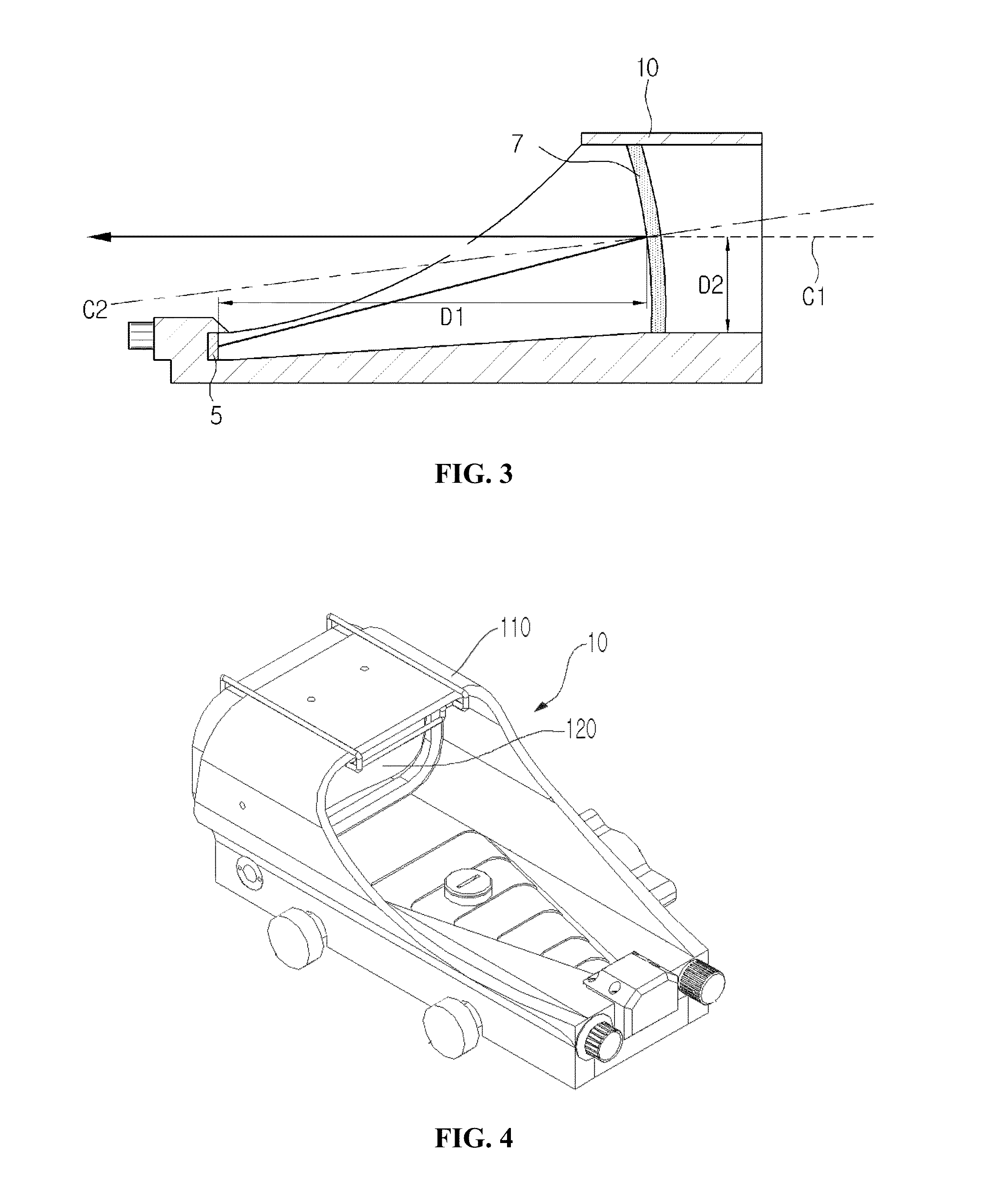
This invention relates to a dot-sight device with polarizers. The patent aims to solve the problems of preventing the other party from observing the dipped rays emitted from the dot indication generator and minimizing the parallax of the reflecting mirror. Additionally, the patent also provides the option to remove the polarizing unit in case of an emergency. The technical effects of this invention include reducing the risk of discovery, improving image quality, and securing sufficient quantity of incident light.

Problems solved by technology

However, in the case of the aiming based on only the gun-sight and the foresight, even minor variation and shaking make it difficult to align the line of sight, and also short-distance firing or urgent situation make it difficult to do quick aiming.
That is, such an aimed-shot method requires complicated processes such as target capture and confirmation, alignment in the light of sight, aiming, etc. and requires time.
Further, the foresight and the gun-sight are so small that accurate alignment therebetween is susceptible to minor shaking Moreover, if too much attention is paid to the alignment in the line of sight, the attention is drawn to the foresight and the gun-sight rather than a target or a front view and therefore vision needed for shooting or urgent situations becomes narrower.
Naturally, the excessive parallax deteriorates a hit degree to the target when the dot sight is used.
Accordingly, it is disadvantageously impossible to fully prevent an observer of the dot sight from being exposed.

Method used


Image

  • Dot-sight device with polarizers
  • Dot-sight device with polarizers
  • Dot-sight device with polarizers

Examples


first embodiment

[0040]Below, a dot-sight device with polarizers according to the present invention will be described with reference to accompanying drawings.

[0041]Among the accompanying drawings, FIG. 4 is a perspective view of a dot-sight device with polarizers according to an embodiment of the present invention, FIG. 5 is a rear perspective view of the dot-sight device with the polarizers according to an embodiment of the present invention, and FIG. 6 is a cross-section view of the dot-sight device with the polarizers according to an embodiment of the present invention.

[0042]As shown therein, the dot-sight device with the polarizers according to an embodiment of the present invention includes a housing 110 formed with a main scope tube having a first end portion facing a target and a second end portion facing an observer; a reflecting mirror 120 formed in the first end portion of the main scope tube; a first polarizing unit 130 provided in front of the reflecting mirror 120; a dot indication gene...

second embodiment

[0056]Next, the dot-sight device with the polarizers according to the present invention swill be described.

[0057]Among the accompanying drawings, FIG. 7 shows cross-section views of the dot-sight device with the polarizers according to other embodiments of the present invention, and FIG. 8 is a front view showing a window side in (c) of FIG. 7.

[0058]As shown in FIG. 7, this embodiment of the dot-sight device with the polarizers is different from the foregoing embodiment in that the housing 110 is a close type dot sight as opposed to the foregoing open type housing 110, a window 160 is arranged at a portion opposite to an observer's eyes, the dot indication generator 140 is fastened to the window 160, and the second polarizing unit 150 is provided in front of the dot indication generator 140.

[0059](a) to (c) of FIG. 7 shows different positions where the dot indication generator 140 are located. Here, (a) of FIG. 7 shows that the dot indication generator 140 is arranged at the same po...


PUM


Abstract

Disclosed is a dot-sight device with polarizers. The dot-sight device with polarizers includes: a reflecting mirror; a first polarizing unit provided in front of the reflecting mirror; a dot indication generator emitting a ray to the reflecting mirror to form a the dot virtual image; and a second polarizing unit provided in front of the dot indication generator, the first polarizing unit and the second polarizing unit being arranged so that a ray of the dot indication generator is passed through the second polarizing unit but blocked by the first polarizing unit. Thus, there is provided a dot-sight device with polarizers, in which a ray emitted from a dot indication generator is not discovered by the other party and thus a dot-sight observer is not discovered by the other party.

Description

CROSS-REFERENCE TO RELATED APPLICATION[0001]This application claims the benefit of Korean Patent Application No. 10-2011-0121802, filed Nov. 21, 2011, which is hereby incorporated by reference in its entirety.BACKGROUND OF THE INVENTION[0002]1. Field of the Invention[0003]The present invention relates to a dot-sight device with polarizers, and more particularly to a dot-sight device with polarizers, in which a ray emitted from a dot indication generator is not discovered by the other party, and thus a dot-sight observer is not discovered by the other party.[0004]2. Description of the Related Art[0005]The features of guns such as a rifle, a heavy machine gun, etc. depend on how quick an aimed shot is fired and how accurate a target is aimed. In general, the aiming of the guns is achieved by aligning a line of sight between the gun-sight and the foresight. The aiming based on alignment of the line of sight between the foresight located at an end of a gun barrel and the gun-sight locat...

Claims


Application Information

Patent Timeline
Patent Type & Authority Applications(United States)
IPC IPC(8): F41G1/30
CPCF41G1/30F41G1/027F41G1/34
Inventor JUNG INLEE DONG HEE
Owner JUNG IN
Learn More