
Security monitoring system and method

a security monitoring and monitoring system technology, applied in the field of security monitoring systems and methods, can solve problems such as excessive deployment, and achieve the effect of detecting power consumption

Active Publication Date: 2013-10-03
ADVANERGY
View PDF6 Cites 37 Cited by
  • Summary
  • Abstract
  • Description
  • Claims
  • Application Information

AI Technical Summary

Benefits of technology

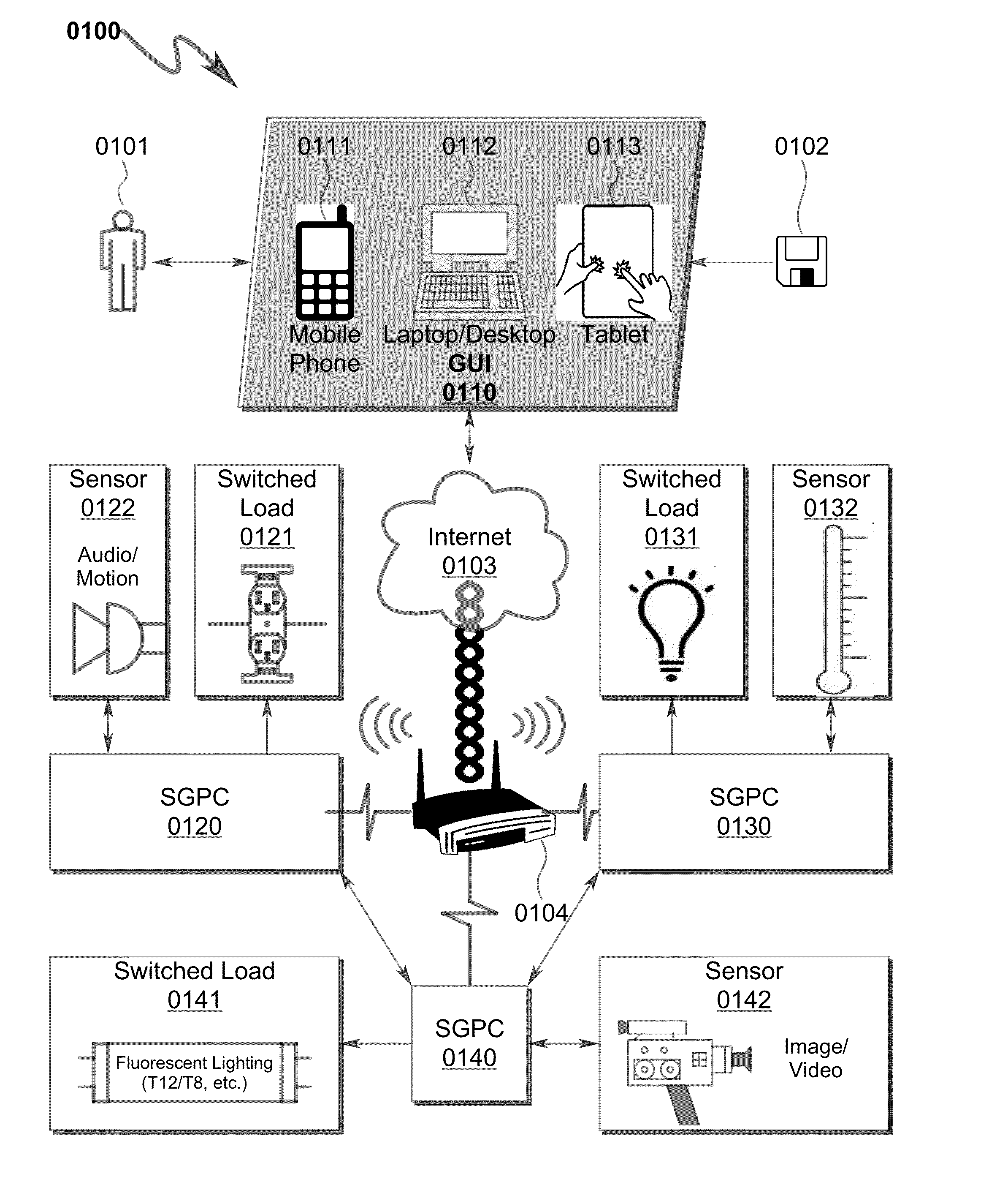
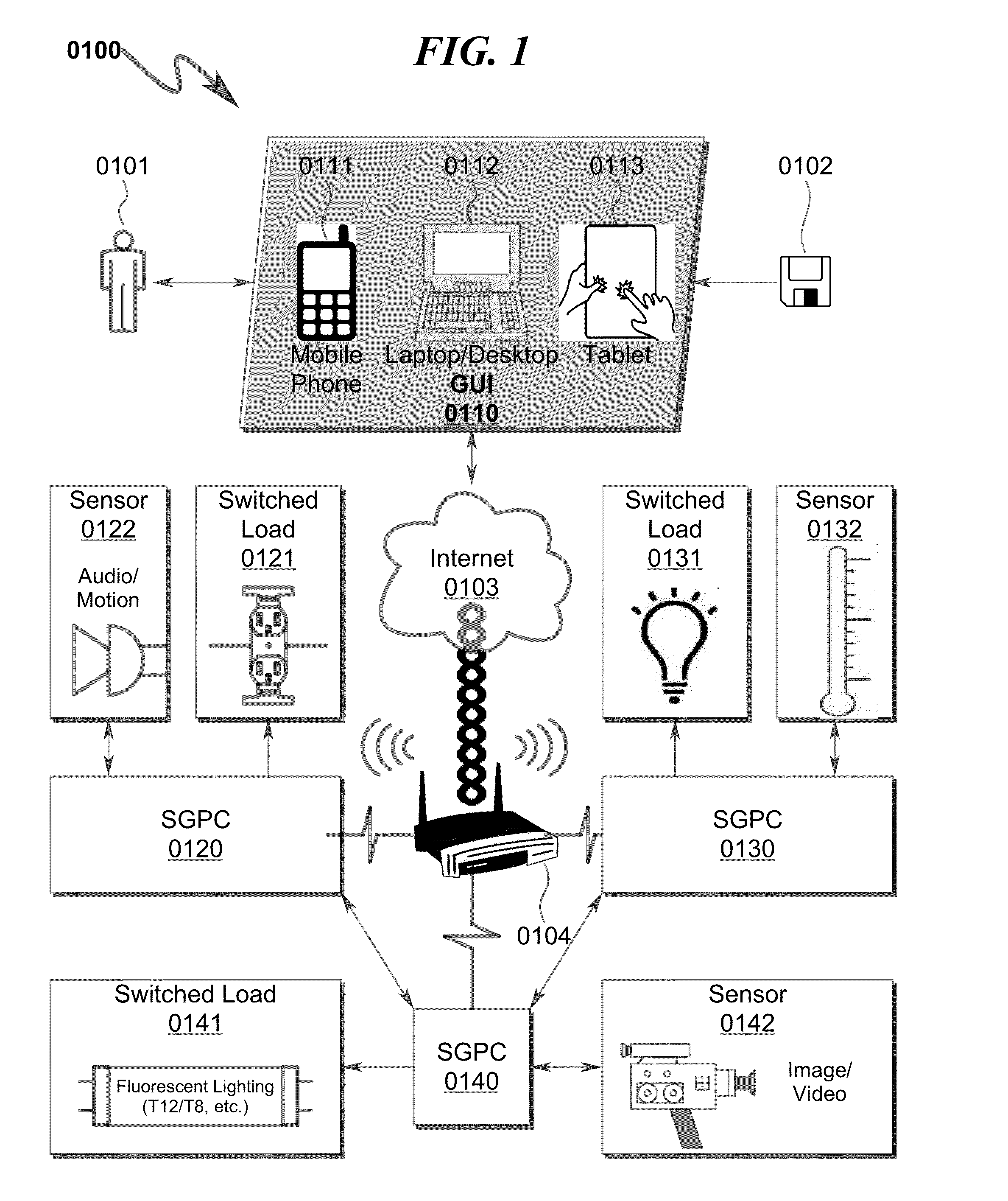
The present invention is a system and method that uses Smart Gateway Power Controller (SGPC) modules to create a mesh network of cooperating security monitoring / control systems. These modules can be retrofit into existing electrical infrastructures to provide Internet-accessible security monitoring and control functions. The SGPC modules can incorporate a wide variety of environmental sensors and control the power to light bulbs as well as provide sensor monitoring. The system provides instant access to both sensor data and lighting control functions via the Internet, eliminating the need for large software development efforts to monitor and control the meshed network of sensors and controls. The SGPC-based security monitoring system can be retrofit into light fixture contexts, providing a cost-effective solution for widespread deployment in critical areas. The system also allows for energy conservation by modulating the operation of lighting fixtures in response to environmental and overall energy monitoring functions. Overall, the invention provides a flexible and efficient solution for security monitoring and control in various environments.

Problems solved by technology

This is particularly true in urban cities, government buildings, airports, and other security-sensitive areas in which security monitoring is desirable, but for cost reasons has not been as extensively deployed as needed.

Method used


Image

  • Security monitoring system and method
  • Security monitoring system and method
  • Security monitoring system and method

Examples


embodiment

Preferred Embodiment Method Summary

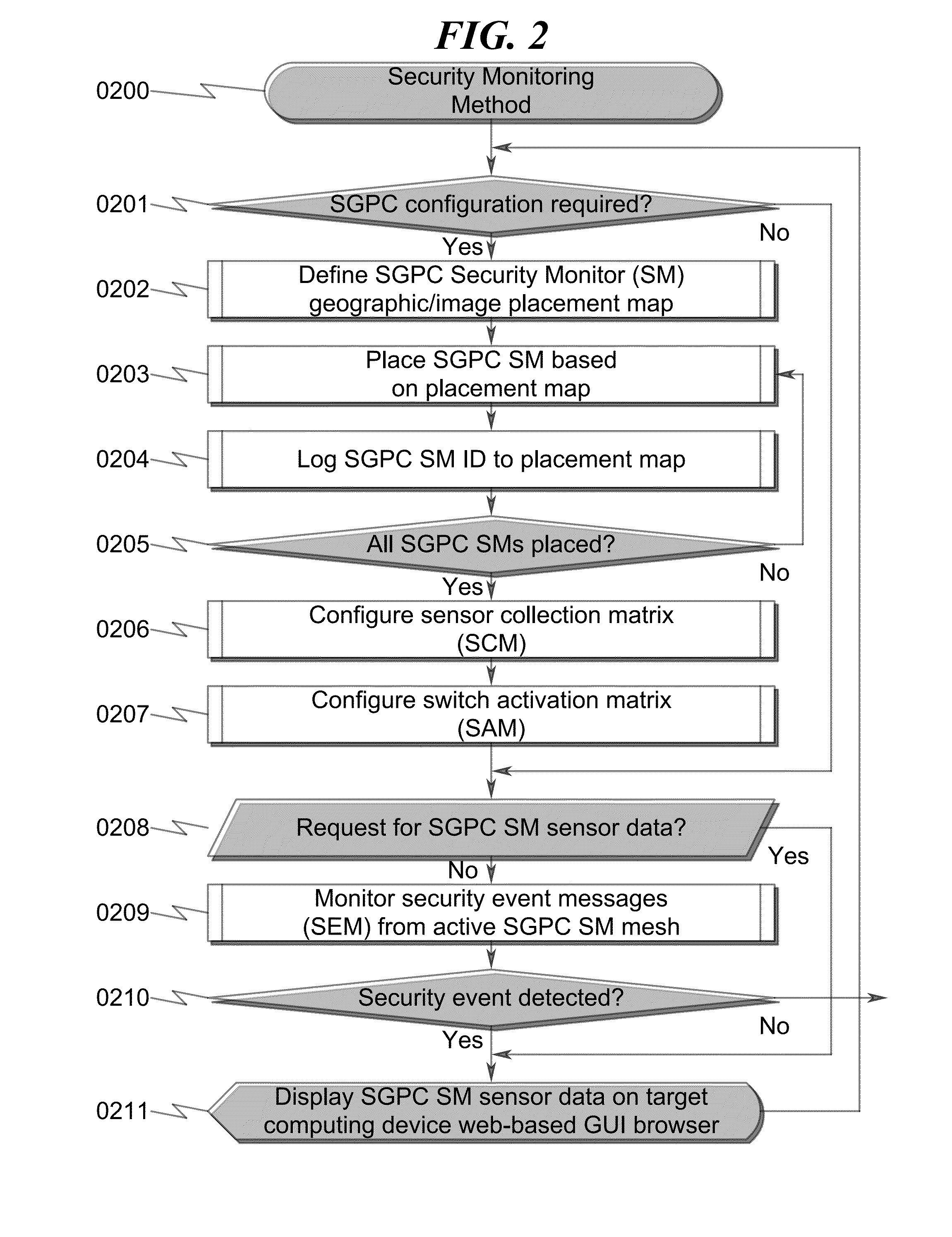
[0293]The present invention preferred exemplary method embodiment anticipates a wide variety of variations in the basic theme of implementation, but can be generalized as a security monitoring method, the method operating in conjunction with a SGPC security monitoring system comprising:[0294](a) source electrical input connector (SEIC); and[0295](b) sink electrical output connector (SEOC);[0296](c) lamp dimmer control (LDC);[0297](d) integrated computing device (ICD);[0298](e) light fixture adapter sensor (LFAS); and[0299](f) wireless communication interface (WCI);[0300]wherein[0301]the SEIC, the SEOC, the LDC, the ICD, the LFAS, and the WCI are contained within a cylindrical housing configured to be installed between an existing electrical lamp and an existing electrical lamp fixture;[0302]the LDC is configured to control the flow of electrical current from the SEIC to the SEOC under direction of the ICD;[0303]the ICD is configured to monitor the ...


PUM


Abstract

A security monitoring system / method implementing distributed Internet-based environmental monitoring and control is disclosed. The system utilizes a smart gateway power controller (SGPC) configured for new / retrofit installation into electrical power distribution networks to allow controlled connection of an AC power source to a customer load device under direction of local or remote Internet direction. The SGPC may also be configured with sensors to detect motion, audio, video, visual images, smoke, carbon monoxide, carbon dioxide, light / darkness, and other environmental data. The SGPC may be configured using a local web-based graphical user interface (GUI) to relay collected sensor information to a remote web browser hosted on a remote computing device. The GUI may incorporate a configuration / setup interface allowing mapping of sensor data to information associated with the sensor location and triggered security reports to occur based on collected sensor data.

Description

CROSS REFERENCE TO RELATED APPLICATIONU.S. CIP Patent Applications[0001]This application is a Continuation-In-Part and incorporates by reference U.S. Utility patent application for LIGHT FIXTURE MONITORING / CONTROL SYSTEM AND METHOD by inventors Jin (nmn) Lu, Todd Scott Kelly, and Lee (nmn) Cheung, filed electronically with the USPTO on Mar. 15, 2013, with Ser. No. 13 / 844,491, EFS ID 15274614, confirmation number 5057, docket AADVN.0107. This parent application will be referred to as “Document LFSM.”U.S. Utility Patent Applications[0002]This application claims benefit under 35 U.S.C. §120 and incorporates by reference U.S. Utility patent application for POWER DISTRIBUTION SYSTEM AND METHOD by inventors Jin (nmn) Lu, Todd Scott Kelly, and Lee (nmn) Cheung, filed electronically with the USPTO on May 31, 2013, with Ser. No. 13 / 907,599, EFS ID 15923884, confirmation number 4847, docket AADVN.0105. This application will be referred to as “Document PDSM.”[0003]This application claims benef...

Claims


Application Information

Patent Timeline
IPC IPC(8): G05B15/02
CPCH04L12/2807H04L12/2836H04L12/66H04L12/2825Y02B70/325Y04S20/228H04L12/2818G05B15/02G05B2219/2642G06F1/26Y02B70/30Y04S20/20
Inventor LU, JINKELLY, TODD SCOTTCHEUNG, LEE
Owner ADVANERGY
Learn More