Vent Valve for Diver's Buoyancy Compensator

a technology of buoyancy compensator and valve body, which is applied in the field of valve body, can solve the problems of valve becoming inoperable, unable to add a pull-cord, and the valve losing all the contained gas

Inactive Publication Date: 2013-10-03
PANDORA UNDERWATER EQUIP
View PDF0 Cites 14 Cited by
  • Summary
  • Abstract
  • Description
  • Claims
  • Application Information

AI Technical Summary

Benefits of technology

[0021]The present invention provides a fail-safe means to operate the valve using any gas or liquid.

Problems solved by technology

The drawback of having three or more vent valves is .that in the event of an undesirable increase in buoyancy, the diver may have to try each valve in turn in order to identify which one releases gas.
That is, operating the button described in the patent would pressurise the pneumatic line to the vent valve, which in turn would cause the valves to lift but there is no means to release the gas pressure in the line described, so the valve would remain lifted and the buoyancy bladder would lose all its contained gas.
Another limitation of the prior art such as in the form, of a vent valve in U.S. Pat. No. 6,217,257 is that the addition of a pull-cord is not feasible to the form described because the cord would normally feed through the device for which a gas tight connection is required for the device in FIG. 2 of U.S. Pat. No. 6,217,257 to operate.
Yet another limitation of the prior art, such as U.S. Pat. No. 6,217,257, is that a loss of pneumatic power would result in the valve becoming inoperable.
Yet another limitation of the prior art, such as U.S. Pat. No. 6,217,257, is that it is not possible to open the valve manually because if the pneumatic supply is shut then to move the Valve would involve pulling a partial vacuum manually.

Method used


Image

  • Vent Valve for Diver's Buoyancy Compensator
  • Vent Valve for Diver's Buoyancy Compensator
  • Vent Valve for Diver's Buoyancy Compensator

Examples


Embodiment Construction

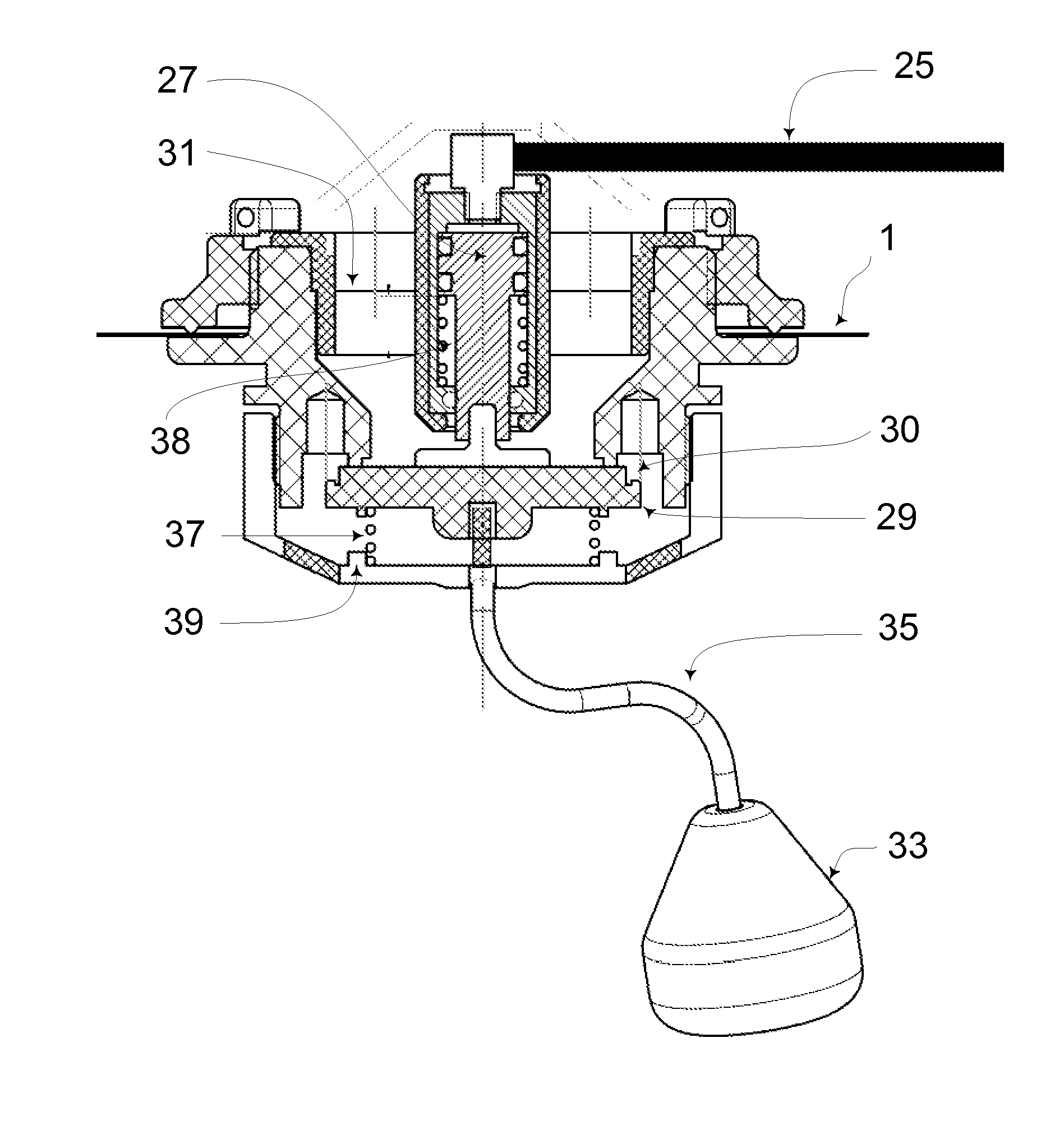
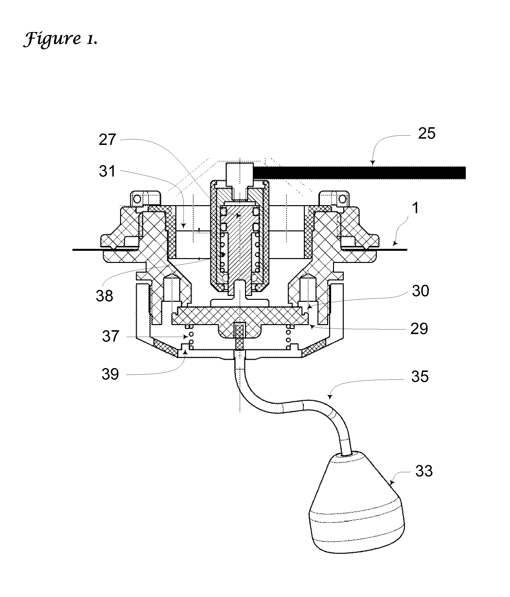
[0025]The invention will now be described in detail .by reference to the aforementioned figures and by use of example embodiments. Reference is made to a BCD bladder. It is not important the form of the bladder the present invention many be applied to many different types of bladder. The sole special requirement for the bladder to be used with the present invention is that the vent valves shall be arranged such that in any orientation of the bladder there is an open gas path from the gas in the bladder to one of the vents: at least three vent valves are required to fulfil this requirement.

[0026]The vent valves in an example embodiment shown in FIG. 1 have a conventional manual pull dump (33) in addition to a pneumatically or hydraulically powered piston (27). The pull dump may be on a cord (35) or a lever.

[0027]A hose (7) carries the gas from the inflator to the actuators is preferably is a narrow bore hose. Kynar hoses are available with a 0.8 mm bore and an outer diameter of 3.6 m...


PUM


Abstract

A vent valve for a buoyancy control device suitable for free-swimming divers, where the valve may be opened both manually and by a powered means, such as from a hydraulic or pneumatic pressure line, the hydraulic or pneumatic pressure being equalised with the ambient pressure when not activated.

Description

TECHNICAL FIELD[0001]The present invention relates to a vent valve for use on a diver's buoyancy jacket, that is either manually operated or automatically operated that operate as a set of at least three valves operating simultaneously.BACKGROUND OF THE INVENTION[0002]Diver's commonly use a Buoyancy Compensation Device (BCD) to compensate for the changes in buoyancy that occur during dive, such as from the compression of the neoprene in a diver's environmental protection suit, or from the consumption of gas in a dive cylinder. A means to add gas to a bladder in the BCD enables the diver's buoyancy to be increased, and vent valves allow gas to be discharged and hence reduce the diver's buoyancy by reduction of the water volume displaced by the bladder.[0003]If a volume of gas is in a bladder underwater, then the gas will not flow out of a vent in the bladder unless the vent is higher than the gas: gas does not flow from a low pressure to a high pressure region on its own. This means ...

Claims


Application Information

Patent Timeline
Patent Type & Authority Applications(United States)
IPC IPC(8): F16K31/00B63C11/02
CPCB63C9/24F16K51/00F16K31/465B63C11/08Y10T137/86485
Inventor BONZON, DAVIDSINCLAIR, ANDREWGLEZ, CHRISTOPHEWEBB, CHRISTOPHER
Owner PANDORA UNDERWATER EQUIP
Why Eureka
Try Eureka