
Measurement head for feeler for workpieces being machined

Active Publication Date: 2013-10-03
BALANCE SYST
View PDF6 Cites 7 Cited by
  • Summary
  • Abstract
  • Description
  • Claims
  • Application Information

AI Technical Summary

Benefits of technology

[0011]Within the scope of this technical task it is an important aim of the invention to obtain a meas

Problems solved by technology

In fact, said measuring heads are expensive and susceptible of malfunction.
At the same manner, eve

Method used


Image

  • Measurement head for feeler for workpieces being machined
  • Measurement head for feeler for workpieces being machined
  • Measurement head for feeler for workpieces being machined

Examples


Example

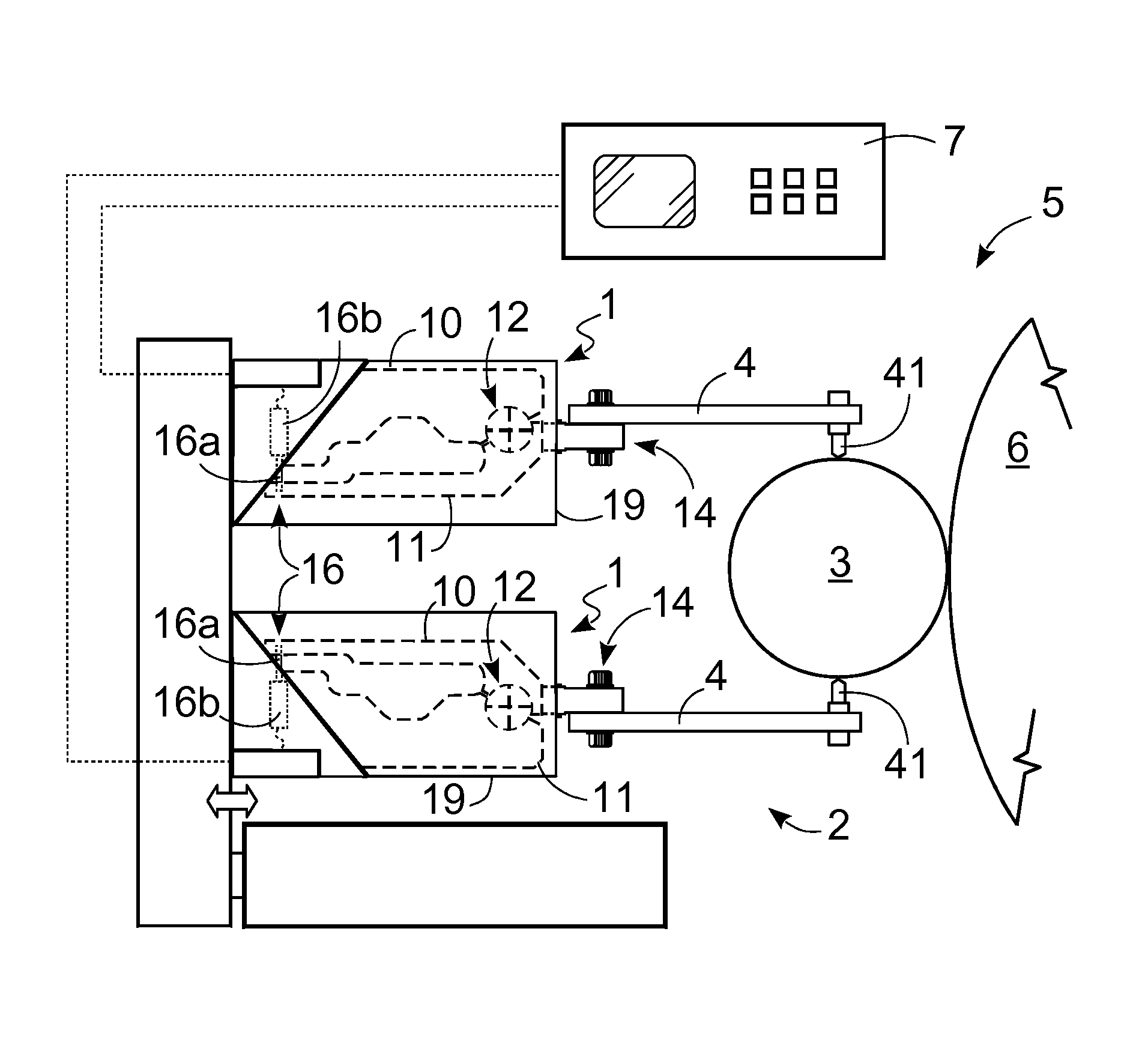
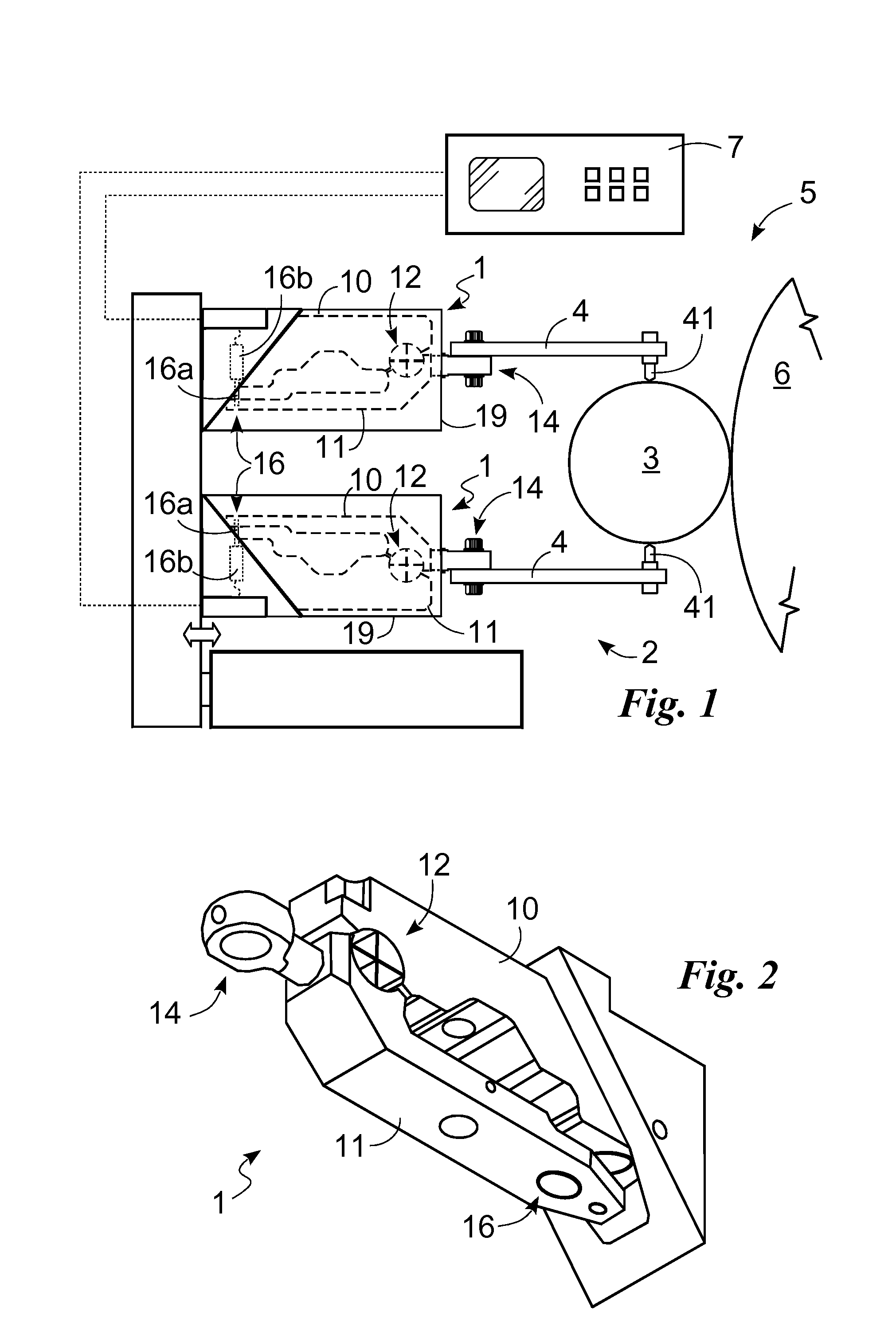
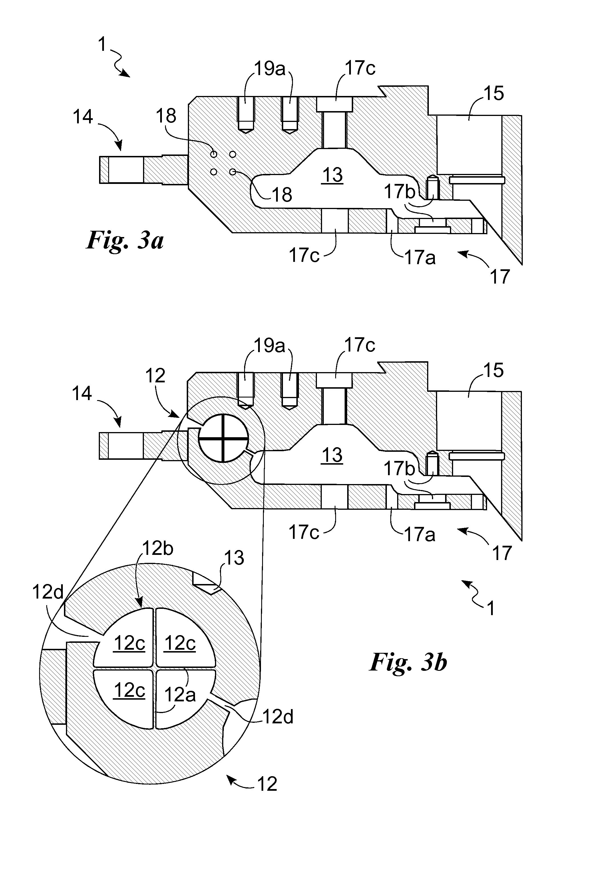
[0018]With reference to the mentioned figures, the measuring head according to the invention is generally identified by reference numeral 1.

[0019]It is suitable for use in a feeler 2 for workpieces 3 being machined.

[0020]Feeler 2 briefly comprises a measuring head 1 and a feeler arm 4, including a contact element 41, consisting of a pin or ball of ceramic material or the like, adapted to feel the workpiece 3 being machined.

[0021]Feelers 2 are in turn part of a measuring device 5 adapted to be used for measuring the accuracy of a chip-removal machining operation while said operation is taking place. The measuring head 1 is therefore adapted to be disposed close to a chip-removal machine tool, in particular a grinding machine comprising a tool 6, such as a grinding wheel for example. Preferably, the measuring head 1 is placed close to a grinding machine for measuring the diameter of the workpiece 3 or for carrying out other measurements such as the axial measurement of a shoulder.

[002...


PUM

PropertyMeasurementUnit
Displacementaaaaaaaaaa

Abstract

Provided is a measuring head (1) for a feeler (2) of workpieces (3) being machined, including a fixed portion (10) to be secured to an outer fixed support, a movable portion (11) including a constraint element (14) for a feeler arm (4), a rotational hinge (12) adapted to connect the fixed portion (10) to the movable portion (11), wherein the fixed portion (10), movable portion (11) and pivot bearing (12) are of one piece construction.

Description

FIELD OF THE INVENTION[0001]The present invention relates to a measuring head for a feeler of workpieces being machined, the measuring head comprising: a fixed portion to be secured to an outer fixed support, a movable portion comprising a constraint element for a feeler arm, a rotational hinge adapted to connect the fixed portion to the movable portion.DESCRIPTION OF THE PRIOR ART[0002]It is known that presently, for checking the sizes and tolerances of a workpiece, in particular during grinding, an appropriate measuring device is used. This device comprises at least one feeler, contacting the surface of the workpiece and connected to a measuring apparatus. The latter, based on displacements of the feeler, detects the sizes and signals them to the machine tool, possibly operating intervention or stoppage thereof.[0003]For instance, for measuring a diameter of a cylindrical grinding shaft, the measuring device is provided with two feelers brought into contact with the workpiece at d...

Claims


Application Information

Patent Timeline
IPC IPC(8): G01B5/08
CPCB24B49/045G01B7/001Y10T29/24G01B5/08G01B7/12
Inventor TRIONFETTI, GIANNI
Owner BALANCE SYST
Learn More