System for Charging an Energy Store, and Method for Operating the Charging System

a technology for charging energy and energy storage, applied in the direction of battery/fuel cell control arrangement, electric devices, battery/cell propulsion, etc., can solve the problems of failure of the energy reservoir, and failure of the entire system, so as to avoid the possibility of undesired torque during the charging operation and reduce the on-state resistance value

Active Publication Date: 2013-09-26
ROBERT BOSCH GMBH
View PDF13 Cites 5 Cited by
  • Summary
  • Abstract
  • Description
  • Claims
  • Application Information

AI Technical Summary

Benefits of technology

[0011]The purpose of the charging device is merely to make available a suitable DC voltage. The charging device can in that regard be implemented in a variety of ways. It can be configured, for example, as a grid-connected charging device. It is also immaterial in this context, with regard to the usability of the exemplary embodiments and / or exemplary methods of the present invention, whether the grid-connected charging device is single- or three-phase, or whether it is configured to be galvanically isolated or nonisolated. If the charging device encompasses a DC voltage converter (DC / DC converter), the latter can be configured for a fixed output voltage as a result of the additional adaptation stage that is created by the coupling units and stator windings operated as a step-down converter; this has an advantageous effect on its efficiency, volume, and cost.
[0012]According to an embodiment of the present invention, provision is made that the negative pole of the charging device is connectable via at least one respective free-wheeling diode to all phases of the electrical machine, and all energy supply branches have a respective contact point that is disposed between two energy reservoir modules and is connectable via at least one free-wheeling diode to the positive pole of the charging device. In this manner, at least two parallel control branches are always available for charging the energy reservoir cells in only one energy supply branch, with the result that lower on-state resistance values can be achieved.
[0013]Undesired torques during the charging operation can be avoided by mechanically blocking the electrical machine during the charging operation, for example with the aid of a linkage detent pawl. Alternatively, the rotor position of the electrical machine can also be monitored, for example with the aid of a corresponding sensor suite, and shut off in the event a rotor motion is detected.

Problems solved by technology

A series circuit of multiple battery cells yields not only a high total voltage but also the problem that the entire energy reservoir fails if a single battery cell fails, since battery current can then no longer flow.
Such a failure of the energy reservoir can result in failure of the entire system.
In a vehicle, a failure of the drive battery can leave the vehicle “stranded.” In other applications, for example rotor blade adjustment of wind power installations, unfavorable boundary conditions such as, for example, high wind can in fact lead to hazardous situations.

Method used


Image

  • System for Charging an Energy Store, and Method for Operating the Charging System
  • System for Charging an Energy Store, and Method for Operating the Charging System
  • System for Charging an Energy Store, and Method for Operating the Charging System

Examples


Embodiment Construction

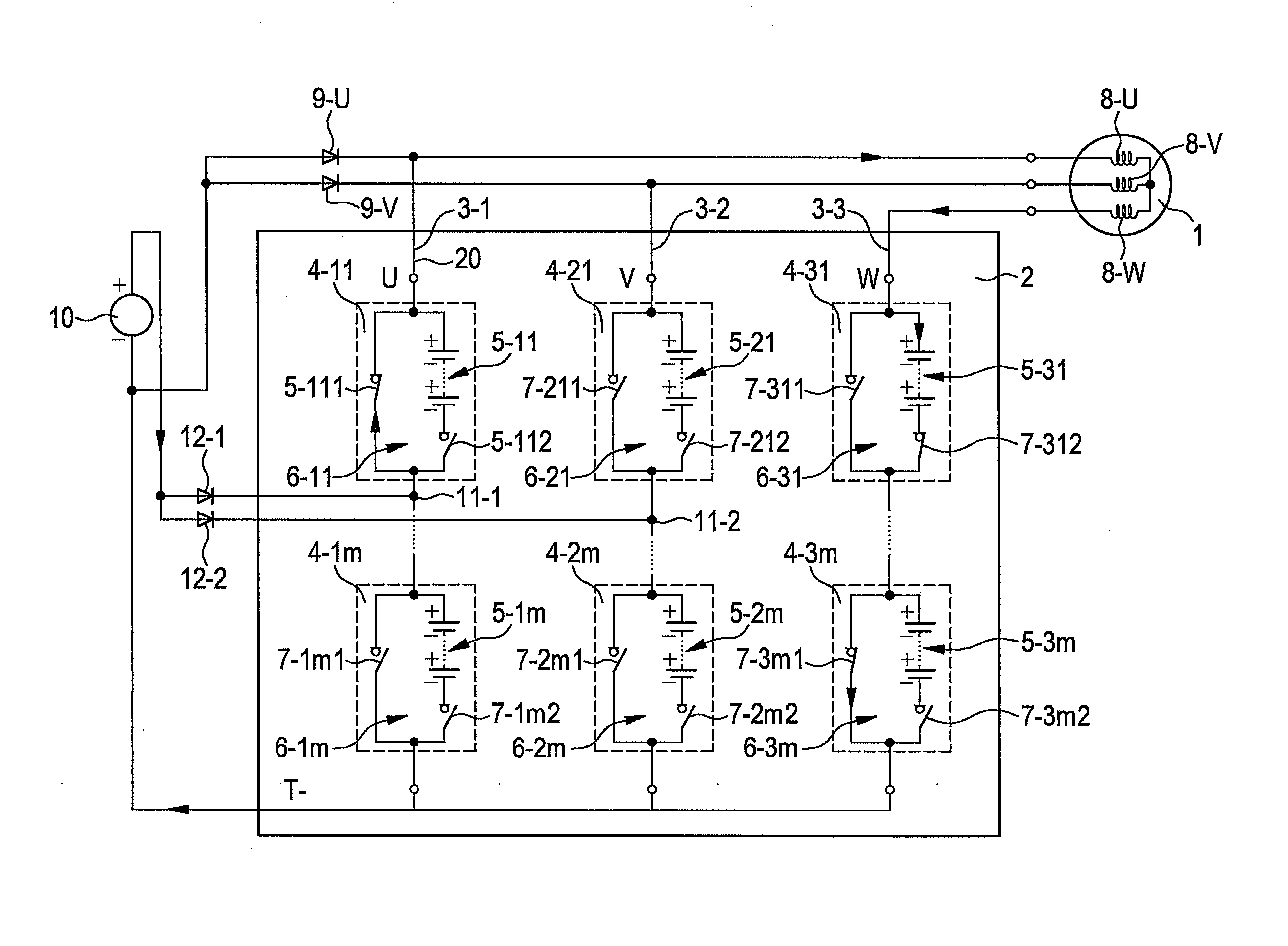
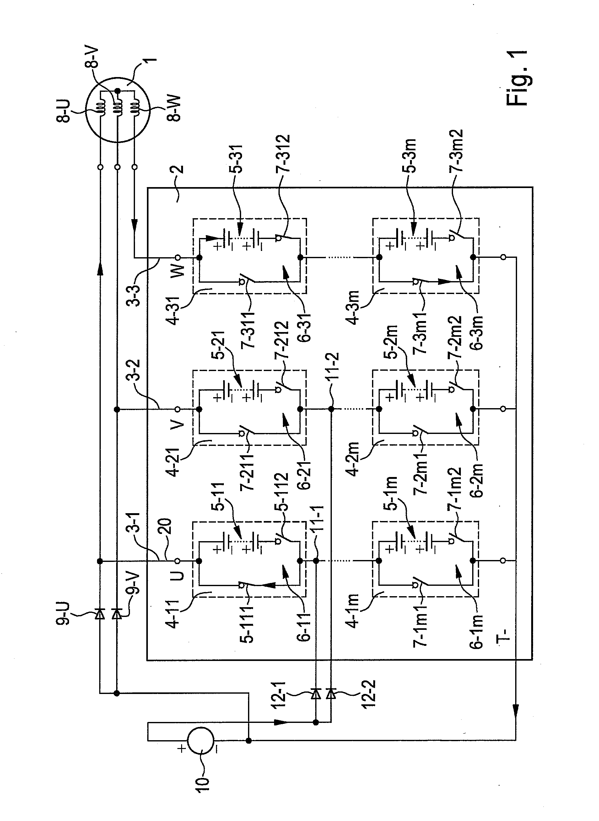
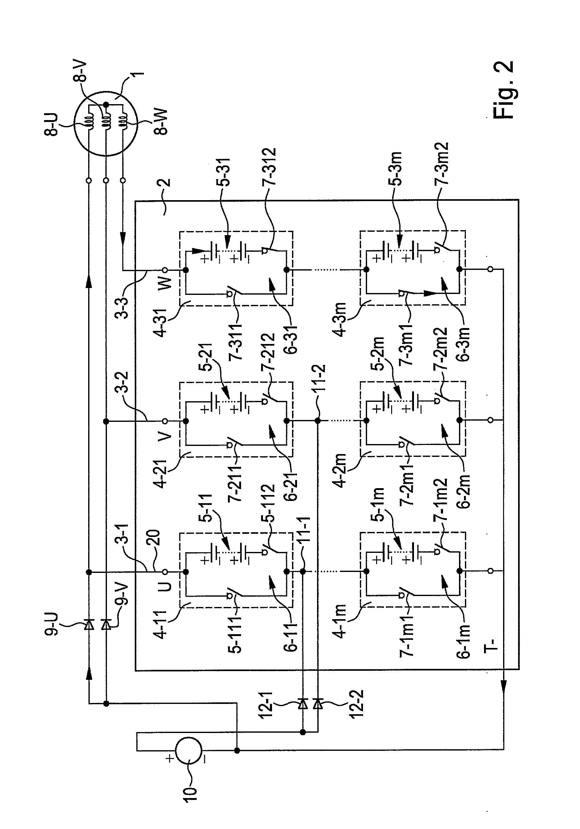
[0018]FIGS. 1 and 2 schematically depict a charging system according to the present invention. A controllable energy reservoir 2 is connected to a three-phase electrical machine 1. Controllable energy reservoir 2 encompasses three energy supply branches 3-1, 3-2, and 3-3, which are connected on the one hand to a reference potential T− (reference bus) that, in the embodiment depicted, carries a low potential, and on the other hand respectively to individual phases U, V, W of electrical machine 1. Each of energy supply branches 3-1, 3-2, and 3-3 has, connected in series, m energy reservoir modules 4-11 to 4-1m, 4-21 to 4-2m, and 4-31 to 4-3m respectively, where m≧2. Energy reservoir modules 4 in turn each encompass multiple respective electrical energy reservoir cells 5-11 to 5-1m, 5-21 to 5-2m, 5-31 to 5-3m connected in series. Energy reservoir modules 4 furthermore each encompass a respective coupling unit 6-11 to 6-1m, 6-21 to 6-2m, 6-31 to 6-3m that is associated with energy reser...


PUM


Abstract

A system for charging at least one energy reservoir cell in a controllable energy reservoir serving to control/supply electrical energy to an n-phase electrical machine (n≧2). The controllable energy reservoir has n parallel energy supply branches each having at least two series connected energy reservoir modules, each encompassing at least one electrical energy reservoir cell having an associated controllable coupling unit, are connected to a reference bus, and are connected to a respective phase of the machine. As a function of control signals, the coupling units interrupt the respective energy supply branch or bypass the associated reservoir cells or switch the associated reservoir cells into the respective energy supply branch. To charge at least one cell, at least two phases of the machine are connectable via at least one respective free-wheeling diode to a negative pole of a charging device. The reference bus is connectable to the negative pole of the device. Those energy supply branches connected to those phases which are connectable to the negative pole of the device each have a contact point disposed between two energy reservoir modules and is connectable via at least one free-wheeling diode to a positive pole of the device.

Description

FIELD OF THE INVENTION[0001]The present invention relates to a system for charging an energy reservoir, and to a method for operating the charging system.BACKGROUND INFORMATION[0002]It is becoming apparent that in the future, both for stationary applications such as wind power installations and in vehicles such as hybrid or electric vehicles, increasing use will be made of electronic systems that combine new energy storage technologies with electrical drive technology. In conventional applications an electrical machine, which is embodied e.g. as a phase-sequence machine, is controlled via a converter in the form of an inverter. A characteristic of such systems is a so-called DC link circuit through which an energy reservoir, usually a battery, is connected to the DC voltage side of the inverter. In order to be able to meet the demands of a particular application in terms of power output and energy, multiple battery cells are connected in series. Because the current furnished by an e...

Claims


Application Information

Patent Timeline
Patent Type & Authority Applications(United States)
IPC IPC(8): H02J7/00
CPCB60L11/18H02J7/007B60L11/1814B60L11/1816B60L11/1864B60L2220/54H02J7/0024H02J7/0055H02J7/1492H02J2007/0059H02J2007/0067Y02T10/641Y02T10/7055Y02T10/92Y02T90/127Y02T90/14Y02T10/7005Y02T10/7094Y02T10/7033Y02T10/7061Y02E10/766B60L11/1803Y02T10/7072B60L53/14B60L50/51B60L53/24B60L58/21H02J2207/20H02J2207/40H02J2310/48H02J2300/28H02J7/0025Y02T10/70Y02T10/64H02J7/0013Y02E10/76Y02T90/12
Inventor FEUERSTACK, PETERWEISSENBORN, ERIKKESSLER, MARTIN
Owner ROBERT BOSCH GMBH
Why Eureka
Try Eureka