Sprocket for easy cleaning

a technology of sprockets and sprockets, which is applied in the direction of conveyors, transportation and packaging, etc., can solve the problems of too abrasive in contact with the belt when used continuously, and less than optimum for other needs, so as to achieve the effect of improving aesthetics and core strength

Inactive Publication Date: 2013-09-05
WHITE OAK IND
View PDF1 Cites 2 Cited by
  • Summary
  • Abstract
  • Description
  • Claims
  • Application Information

AI Technical Summary

Benefits of technology

[0005]These needs and others are satisfied by a sprocket embodying features of the invention. The sprocket comprises an exterior skin (exterior here on) and an integrally molded interior core. The exterior is molded of a first plastic material, and the core is molded of a second plastic material. In this way, the sprocket can combine the advantageous properties of both materials to better address a given application.
[0011]in another aspect of the invention, a method for molding a sprocket is provided. The co-injection or sandwich method is used to produce this invention. According to the method, a first plastic material is injected into a cavity defined by inner walls of a sprocket mold to form an exterior coating the walls. A second plastic material is injected into the sprocket mold cavity inside the exterior. Pressure and heat are applied to the mold to form the sprocket. This gives the sprocket higher core strength and improved aesthetics.

Problems solved by technology

In some instances, the properties of a single material may serve some of the needs of an application well, but may be less than optimum for other needs.
For example, in an abrasive environment, a sprocket made entirely of polyurethane or nylon which has good abrasion-resistant properties, but may be less than optimum for other needs.
As another example, glass-filled materials provide strength and firmness to plastic articles, but are too abrasive in contact with a belt when used continually.
But this design is only partially solving the problem since the critical hinge areas are still covered by the sprocket rim to a certain extent, when engaged on the sprocket.

Method used


Image

  • Sprocket for easy cleaning
  • Sprocket for easy cleaning
  • Sprocket for easy cleaning

Examples


Embodiment Construction

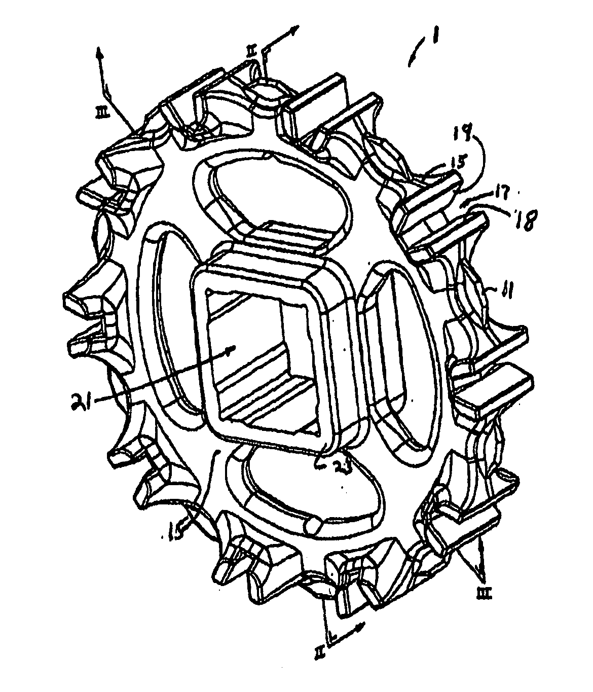
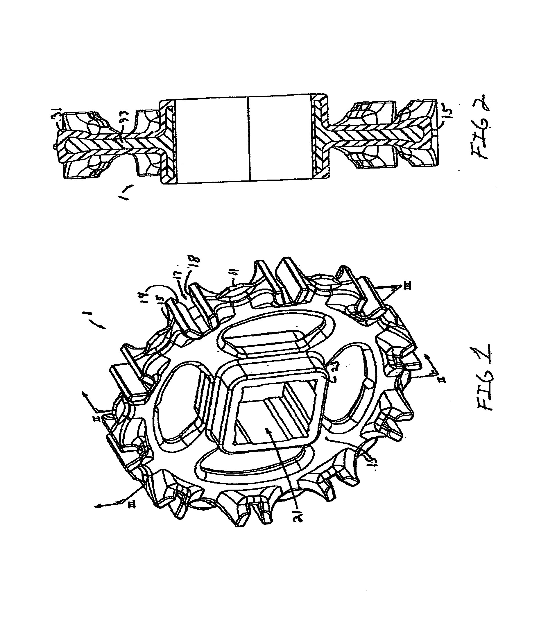
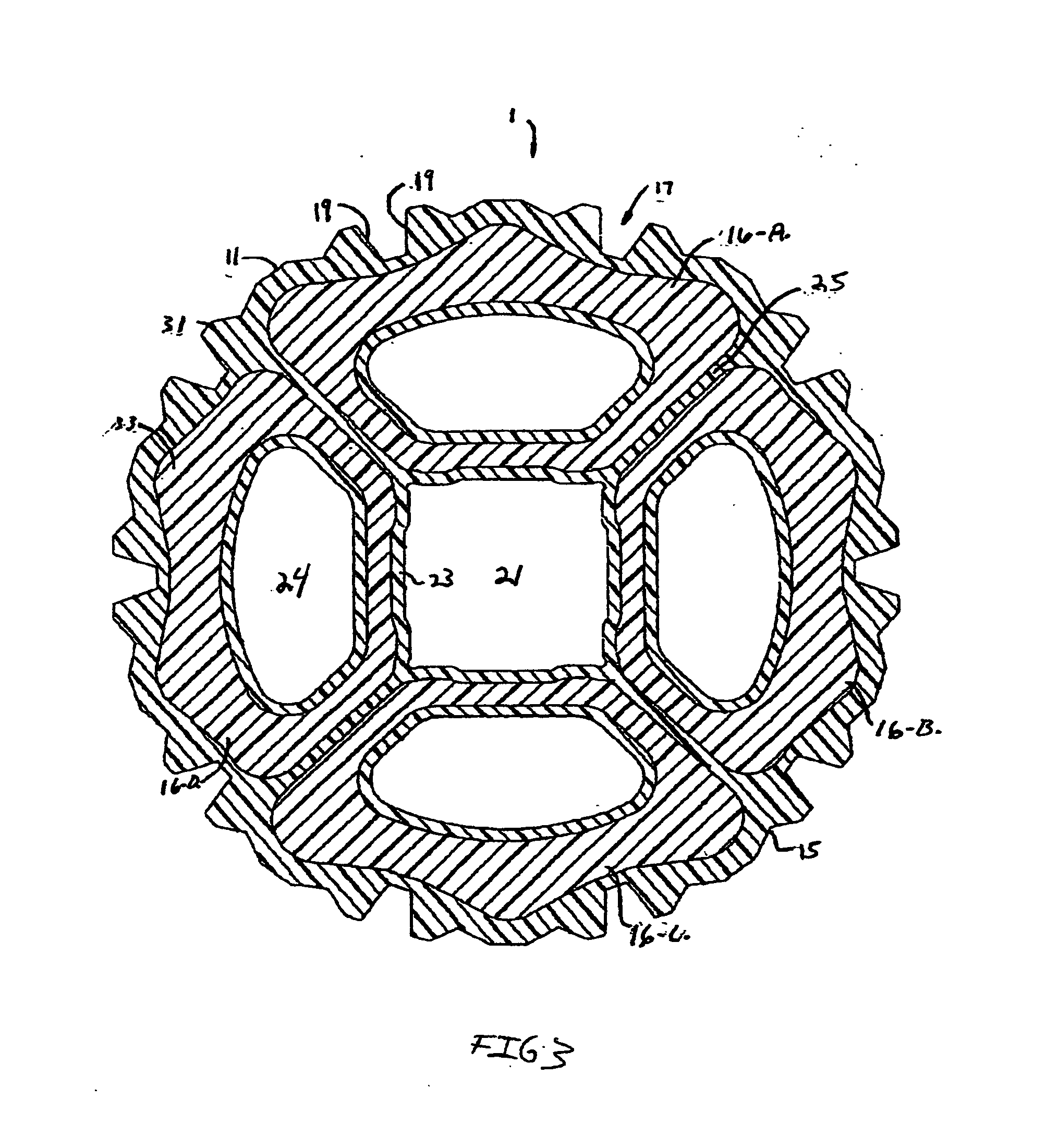
[0017]Ten tracking teeth 11 are spaced around the circumferential periphery 15 of the sprocket. Midway between consecutive tracking teeth are grooves 17 with leading and trailing driving surfaces 19, 18 for engaging complementary drive surfaces on a modular plastic conveyor belt. The sprocket also forms a central axial bore 21, shown as generally square to receive a square shaft. A hub 23 around the bore extends axially in the width direction of the sprocket farther than the other parts of the sprocket. Spokes 25 extend from the hub to the outer periphery and divide the sprocket into four regions 16A-D. An opening 24 formed in each region makes the sprocket easy to clean and lighter in weight.

[0018]As illustrated in the cross sections of FIGS. 2 and 3, the sprockets, which include an exterior 31 and an interior core 33, are made of two materials. The teeth, the peripheral structure, and the exterior of the sprocket are made of a first plastic material. The interior core, which inclu...


PUM


Abstract

A two-material plastic sprocket for modular plastic conveyor belts and an associated method for molding such a sprocket. The sprocket is made of a first plastic material forming the exterior and a second plastic material forming the interior core using co-injection molding. The invention relates generally the sprockets used to drive modular plastic conveyor belts and, more particularly, to sprockets molded out of two plastic materials.

Description

BACKGROUND OF INVENTION[0001]the present invention relates to a modular conveying apparatus. The invention relates generally the sprockets used to drive modular plastic conveyor belts and, more particularly, to sprockets molded out of two plastic materials.[0002]Modular plastic conveyor belts are used in a wide range of conveyor applications. Unlike flat belts, which are driven by tensioned rollers or pulleys, modular plastic conveyor belts are driven by sprockets, which positively engage drive structure in the belts. The most common sprockets are molded or machined out of one homogeneous plastic or metal material. In this instance the sprocket material is chosen to best match the application. In some instances, the properties of a single material may serve some of the needs of an application well, but may be less than optimum for other needs. For example, in an abrasive environment, a sprocket made entirely of polyurethane or nylon which has good abrasion-resistant properties, but ...

Claims


Application Information

Patent Timeline
Patent Type & Authority Applications(United States)
IPC IPC(8): B65G23/06
CPCB65G23/06
Inventor HARRELSON, ANTHONY T.
Owner WHITE OAK IND
Why Eureka
Try Eureka