Driving control apparatus mounted on vehicle to avoid collision with preceding vehicle
a technology of driving control and vehicle, which is applied in the direction of process and machine control, braking systems, instruments, etc., can solve the problems of difficult to move the present vehicle towards the region, the present vehicle cannot reliably avoid obstacles in front of the present vehicle, and the likelihood of colliding with other vehicles approaching from the behind
- Summary
- Abstract
- Description
- Claims
- Application Information
AI Technical Summary
Benefits of technology
Problems solved by technology
Method used
Image

Examples
first embodiment
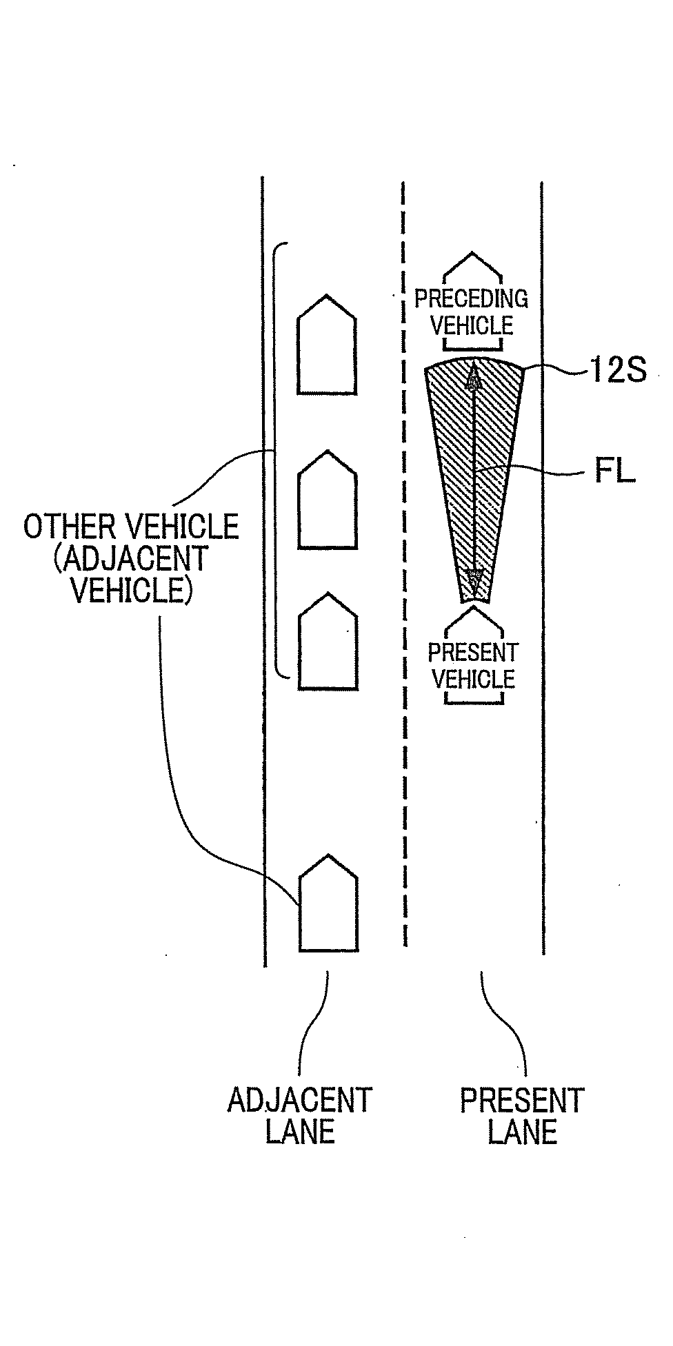
[0035]With reference to FIGS. 1 to 4, hereinafter is described an on-vehicle driving control apparatus 1 according to the first embodiment of the present disclosure. The on-vehicle driving control apparatus 1 is mounted on a present vehicle and constitutes a part of a tracking control system used for a tracking drive operation in which a present vehicle is driven so as to track a preceding vehicle that exists (running) ahead of the present vehicle. For instance, the tracking drive operation is accomplished with an adaptive cruise control (hereinafter described as ACC) in which the traveling speed of the present vehicle and an inter-vehicle distance between the present vehicle and the preceding vehicle are adjusted.
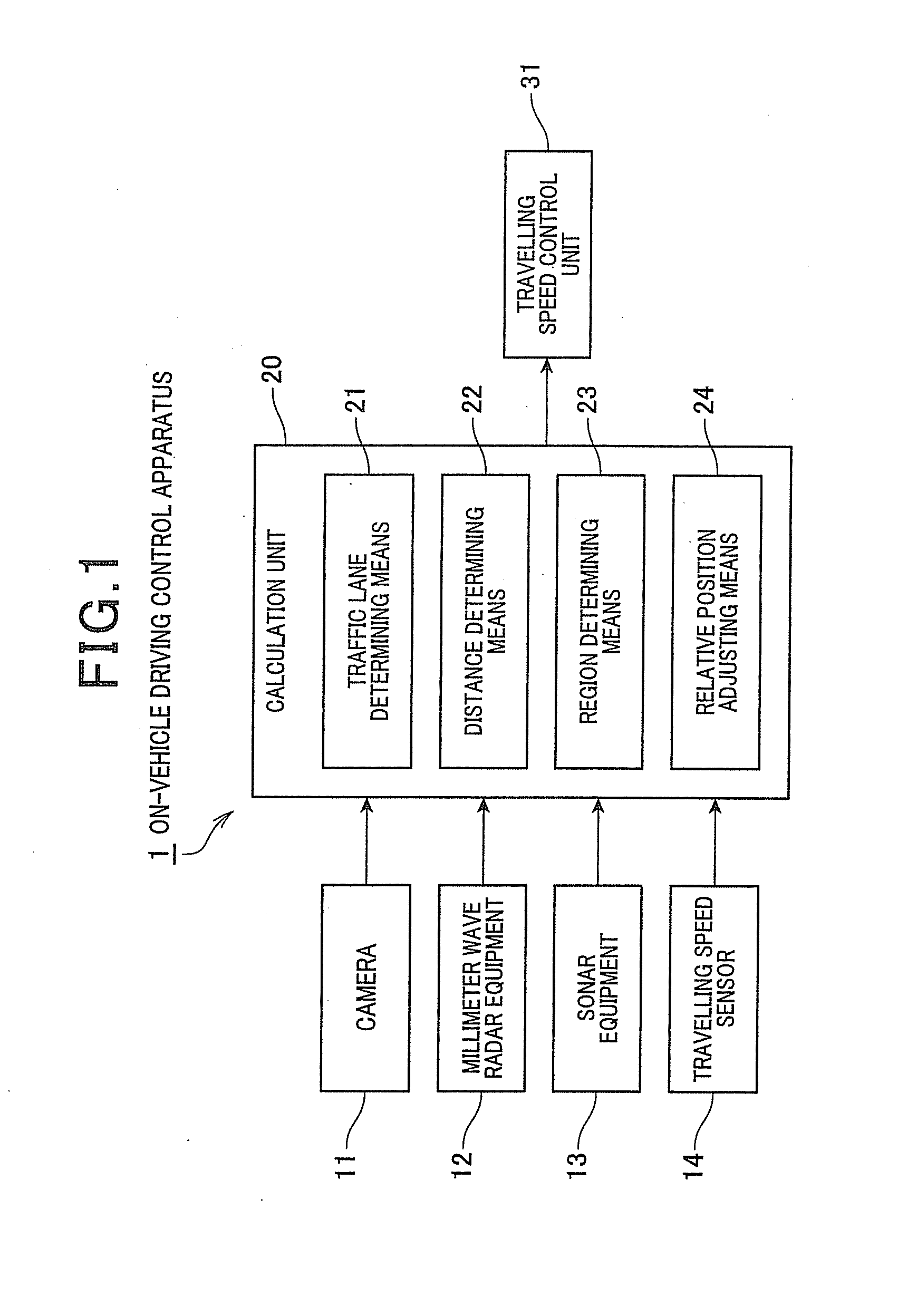
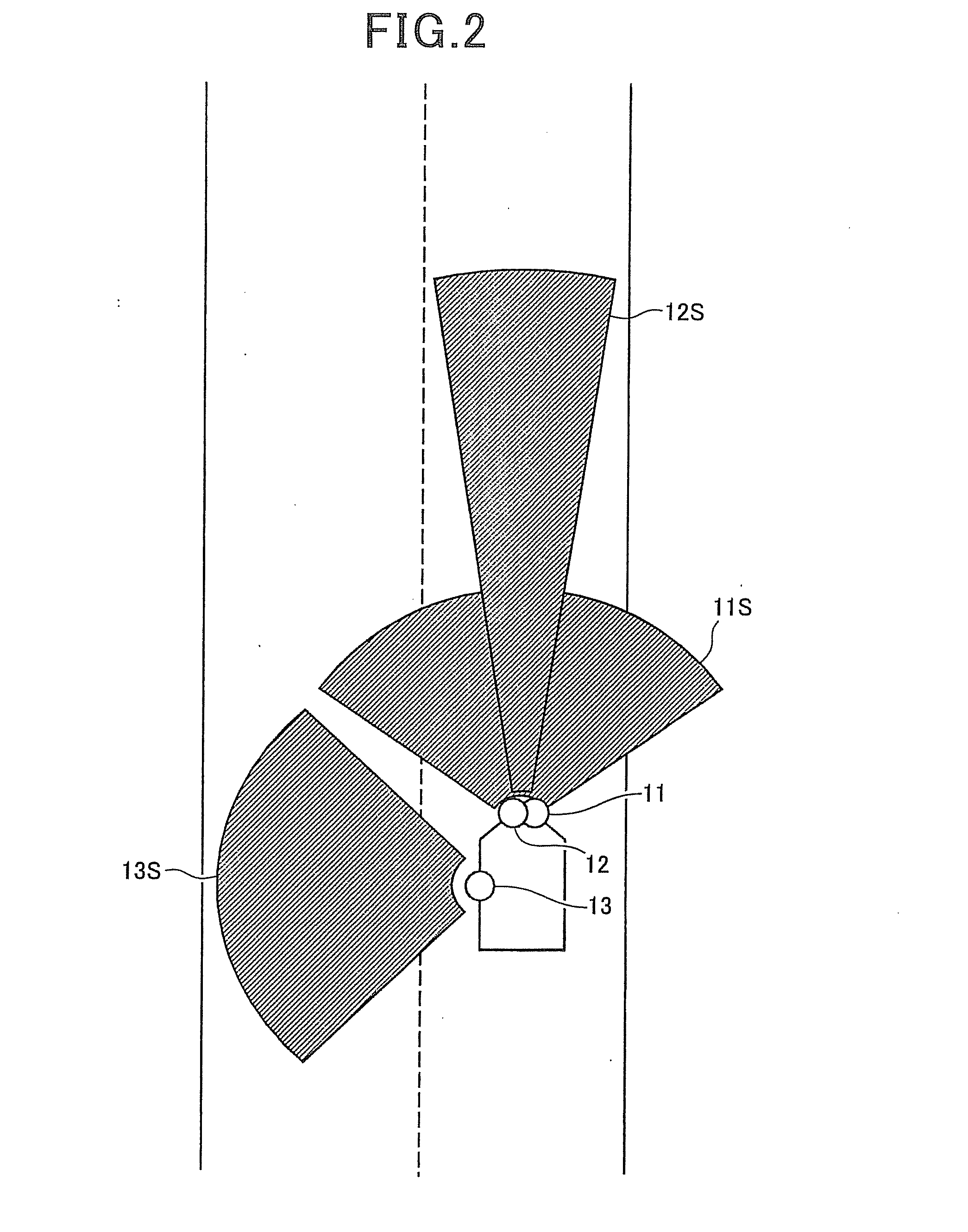
[0036]As shown in FIG. 1, the on-vehicle driving control 1 (driving control apparatus) includes a camera 11 (traffic lane determining means) that detects a traffic lane, a millimeter wave radar equipment 12 (vehicle detecting means, region detecting means, distance determi...
second embodiment
[0067]Next, with reference to FIGS. 5 and 6, the second embodiment of the present disclosure is described as follows.
The configuration of the on-vehicle driving control apparatus according to the second embodiment is identical to the configuration of the first embodiment. However, in the second embodiment, adjusting the relative position of the present vehicle is further applied compared to the configuration of the first embodiment. Therefore, in the second embodiment, with reference to FIGS. 5 and 6, a controlling of the relative position to be adjusted is mainly described and explanations of other configurations are omitted.
[0068]As shown in FIG. 5, the on-vehicle driving control apparatus 101 includes a camera 11 used for detecting traffic lane, a millimeter wave radar equipment 12 used for detecting the safe inter-vehicle distance between the present vehicle and the preceding vehicle, and the forward avoidance region, a sonar equipment 13 used for detecting the avoidance region,...
third embodiment
[0080]Next, with reference to FIG. 7 and FIG. 8, the third embodiment of the present disclosure is described as follows. The overall configuration of the on-vehicle driving control apparatus according to the third embodiment is the same as the one of the second embodiment, however, the configuration of the third embodiment differs from the one of the second embodiment in the control method for adjusting the relative position of the present vehicle. Hence, according to the third embodiment, only the control method for adjusting the relative position of the present vehicle is described and the explanation for the other elements and the like are omitted.
[0081]As shown in FIG. 7, the on-vehicle driving control apparatus 201 includes a camera 11 used for detecting the traffic lane, a millimeter wave radar equipment 12 used for detecting the forward safe inter-vehicle distance and the forward avoidance region, a sonar equipment 13 used for detecting the avoidance region, a traveling speed...
PUM
 Abstract
Description
Claims
Application Information
 - R&D
- Intellectual Property
- Life Sciences
- Materials
- Tech Scout
- Unparalleled Data Quality
- Higher Quality Content
- 60% Fewer Hallucinations
Browse by: Latest US Patents, China's latest patents, Technical Efficacy Thesaurus, Application Domain, Technology Topic, Popular Technical Reports.
© 2025 PatSnap. All rights reserved.Legal|Privacy policy|Modern Slavery Act Transparency Statement|Sitemap|About US| Contact US: help@patsnap.com