Working Machine

Inactive Publication Date: 2013-08-29
HITACHI CONSTR MASCH CO LTD
View PDF7 Cites 3 Cited by
  • Summary
  • Abstract
  • Description
  • Claims
  • Application Information

AI Technical Summary

Benefits of technology

The invention is about a vehicle that has a space between the rear window of the operator's cab and the engine room ceiling, which makes the operator's seat more comfortable and allows for better handling. This space also allows the operator to have a wider rearward visual field, improving performance while performing work while looking at the rear of the vehicle.

Problems solved by technology

Thus, the height of the engine room tends to increase as the number of devices installed in the engine room increases or the size of each device increases.

Method used


Image

  • Working Machine
  • Working Machine
  • Working Machine

Examples


Embodiment Construction

[0029]Embodiments of a working machine according to the invention will be described below with reference to the drawings.

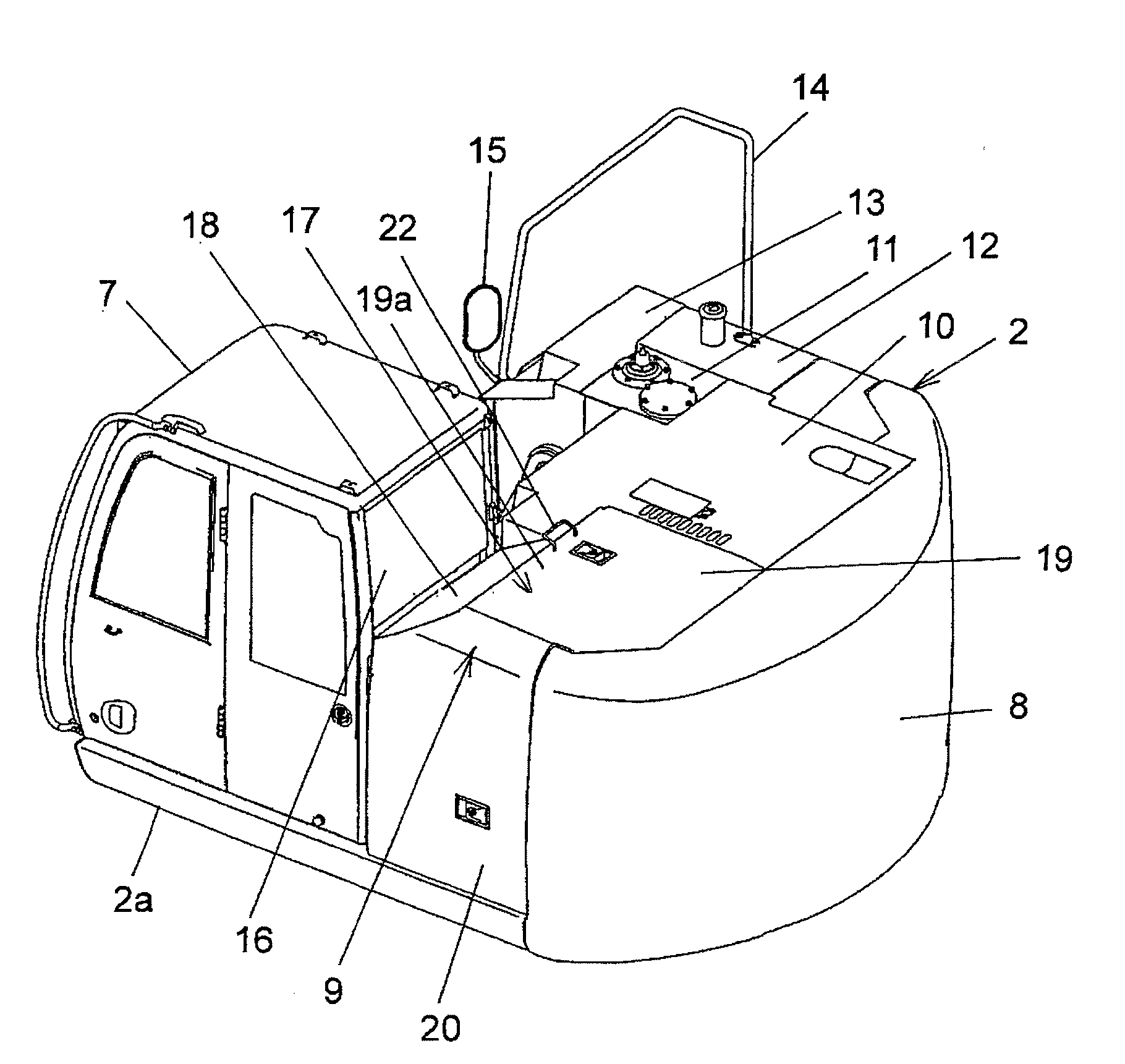
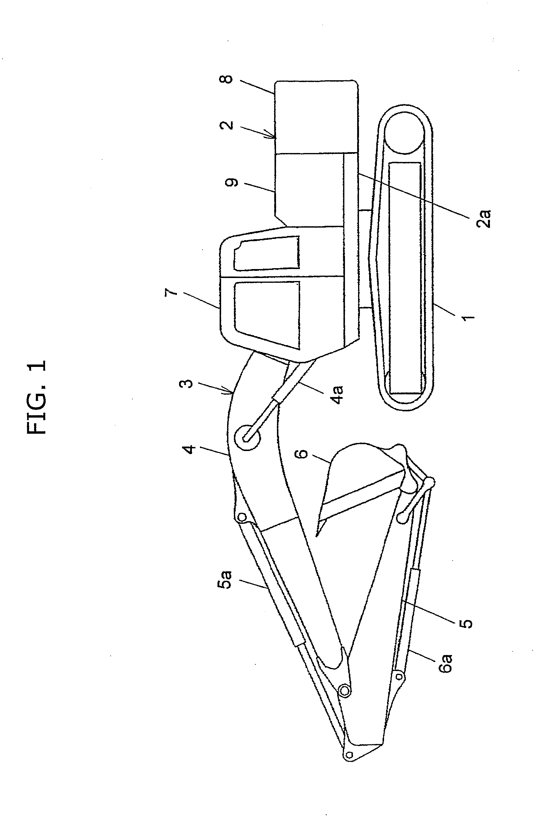
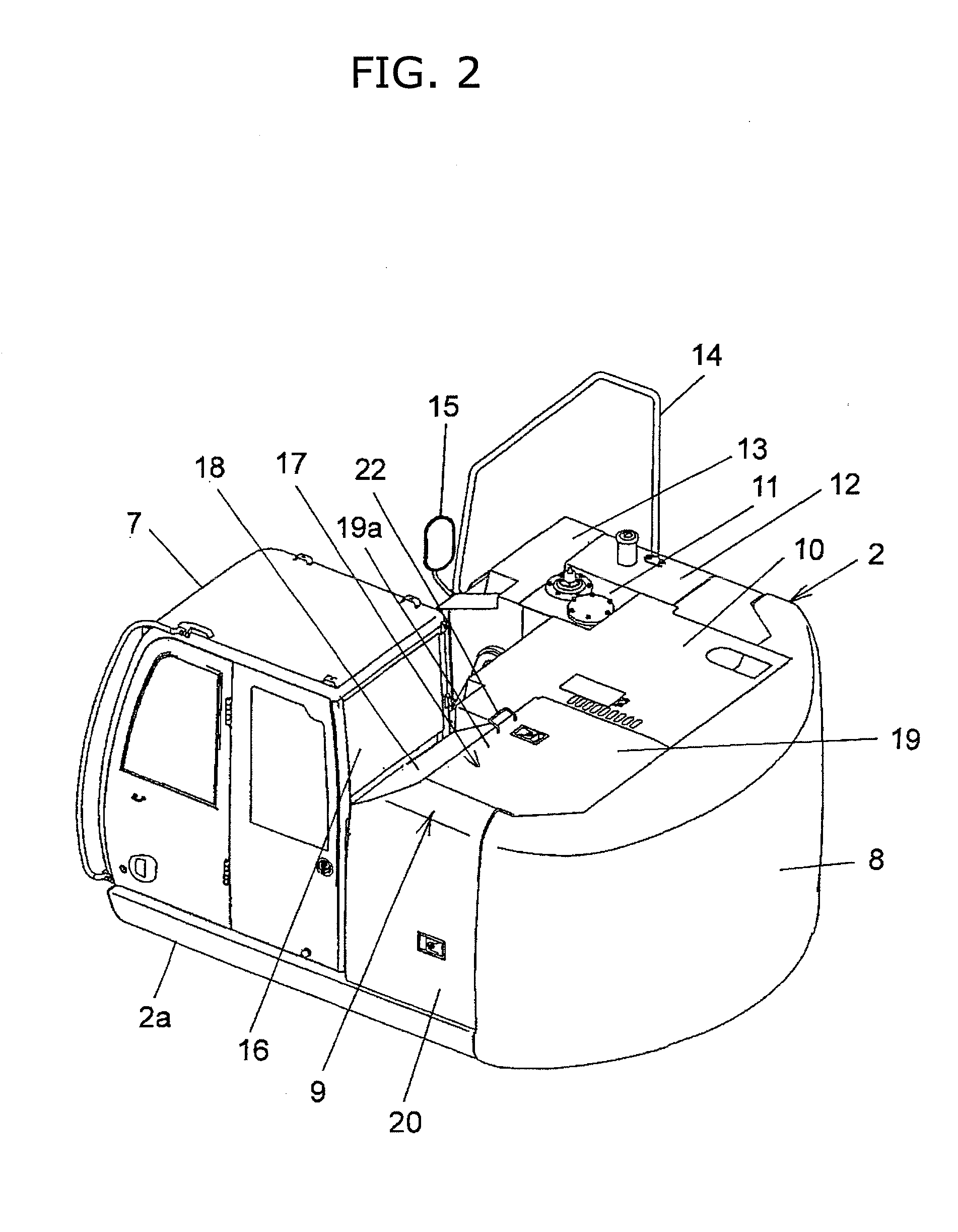
[0030]FIG. 1 is a side view showing a hydraulic excavator formed as a first embodiment of a working machine according to the invention. FIG. 2 is a perspective view showing a revolving upperstructure provided in the hydraulic excavator shown in FIG. 1. FIG. 3 is an enlarged side sectional view of main part of the revolving upperstructure shown in FIG. 2.

[0031]For example, the working machine according to the first embodiment of the invention is made of a hydraulic excavator. As shown in FIG. 1, the hydraulic excavator has: a traveling base 1; a revolving upperstructure 2 which is disposed on the traveling base 1; and a working device 3 which is attached to the revolving upperstructure 2 so as to be rotatable vertically. The working device 3 has: a boom 4 which is attached to the revolving upperstructure 2 so as to be rotatable vertically; a boom cylinder 4a which ...


PUM


Abstract

A hydraulic excavator includes: a revolving upperstructure; a working device attached to the revolving upperstructure; an operator's cab which has a rear window and is disposed in a front position of the revolving upperstructure; and an engine room which is disposed in a rear position adjacent to the operator's cab and has a ceiling part made of a cover member. A part of the cover member located near the operator's cab is made of an inclined surface part having a shape whose height gradually increases toward the rear of a vehicle body with the vicinity of a lower end part of the rear window as a start point during a predetermined distance immediately after the operator's cab. The height of the start point of the inclined surface part may be set equal to or lower than the height of the lower end part of the rear window.

Description

TECHNICAL FIELD[0001]The present invention relates to a working machine such as a hydraulic excavator, in which an operator's cab having a rear window and an engine room adjacent to the operator's cab are disposed on a revolving upperstructure.BACKGROUND ART[0002]Because of working environment, etc., a working machine provided with a revolving upperstructure, such as a hydraulic excavator, is restricted by the width of the revolving upperstructure and the size of rearward protrusion of a counter weight disposed at the rear of the revolving upperstructure in order to prevent the slewing radius from coming out of the vehicle width of a traveling base if possible. Accordingly, for example, in the case where a ventilation area of a heat exchanger received in an engine room disposed on the revolving upperstructure is intended to be set large, the height of the engine room needs to be set large. Particularly, it has become recently necessary to install an exhaust gas disposal device or a ...

Claims


Application Information

Patent Timeline
IPC IPC(8): E02F9/08E02F9/16E02F3/30
CPCB62D25/10B62D33/0617E02F9/0833E02F9/16E02F9/163E02F3/30E02F9/0866E02F9/0891E02F9/00E02F9/08
Inventor SHIMIZU, TSUYOSHINAKAMURA, MASAOKUMAGAI, HIROSHI
Owner HITACHI CONSTR MASCH CO LTD
Why Eureka
Try Eureka