
Apparatus and system for emitting light using a grid light engine

a technology of grid light and apparatus, applied in the field of lighting, can solve the problems of not providing a full spectrum of light similar to sunlight, light fixtures using rgb/rgba modules do not reproduce natural sunlight particularly well, and the practicality of using natural light to illuminate spaces is not always practical

Active Publication Date: 2013-08-29
ARKALUMEN
View PDF4 Cites 27 Cited by
  • Summary
  • Abstract
  • Description
  • Claims
  • Application Information

AI Technical Summary

Benefits of technology

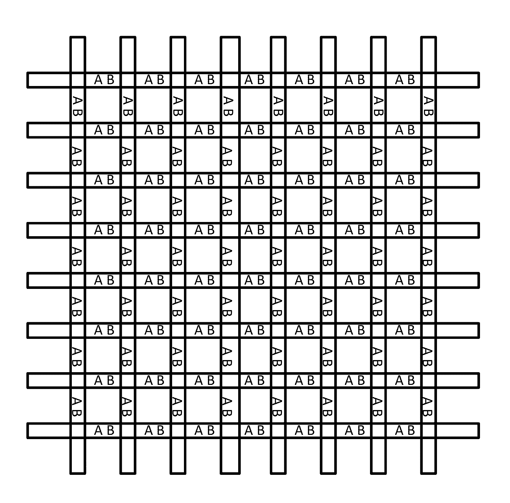
The present invention relates to a lighting apparatus comprising a plurality of elongated segments, which when interconnected together, form a grid light engine. Each segment comprises a plurality of groups of LEDs on both sides, which when emitted, create light inwardly to a plurality of grid squares. The lighting apparatus also includes a back panel light engine which is adjacent to the grid, and operable to emit light through the grid. The invention also includes a lighting apparatus wherein the first set of LEDs emits light in a first direction and the second set of LEDs emits light in a second direction. The first set of LEDs includes at least one first type of LED, while the second set of LEDs includes at least one second type of LED, which emission different light spectrums. The technical effect of this invention is the creation of a lighting apparatus that can emit light in multiple directions and with different light spectrums, providing greater flexibility and control in the creation of lighting effects.

Problems solved by technology

Although these white LEDs can provide sufficiently high quality “white” light for many applications, they do not provide a full spectrum of light similar to sunlight.
Despite the addition of different spectrums mixed together, light fixtures using RGB / RGBA modules do not replicate natural sunlight particularly well.
Unfortunately, using natural light to illuminate spaces is not always practical and artificial lighting is required.

Method used


Image

  • Apparatus and system for emitting light using a grid light engine
  • Apparatus and system for emitting light using a grid light engine
  • Apparatus and system for emitting light using a grid light engine

Examples


Embodiment Construction

[0028]The present invention is directed to apparatus and system for emitting light using a grid light engine. In particular embodiments of the present invention, a light fixture is formed using components that allow for different sets of Light Emitting Diodes (LEDs) to be projected in different directions. When the different sets of LEDs emit different spectrum outputs, the light fixture can appear visually different depending upon the viewers' perspective. When the different sets of LEDs are controlled separately, the light fixture can be used to generate various visual effects including, but not limited to, the appearance of sunrises, afternoon sky and sunsets over a day. In some embodiments, the architecture of the present invention can allow for the perception of significant depth to a viewer, despite the entire light fixture possibly being only a few inches deep.

[0029]The light fixtures according to various embodiments of the present invention comprise a plurality of elongated ...


PUM


Abstract

Lighting apparatus may comprise elongated segments interconnected perpendicularly to form a grid light engine, each segment comprising groups of LEDs on both sides such that, when interconnected together, the grid light engine is operable to emit light inwardly to a plurality of grid squares formed by the segments. The apparatus may further comprise a back panel light engine comprising LEDs, the back panel light engine being coupled adjacent to the grid and operable to emit light from its LEDs through the grid. This architecture can allow for light from different sets of LEDs to be projected in different directions. When the different sets of LEDs emit different spectrum outputs, the light fixture can appear visually different depending upon the viewers' perspective. When the different sets of LEDs are controlled separately, visual effects such as the appearance of depth, sunrises and sunsets can be generated.

Description

CROSS-REFERENCE TO RELATED APPLICATION[0001]The present application claims the benefit under 35 USC 119(e) of 5 U.S. Provisional Patent Application 61 / 558,914 filed on Nov. 11, 2011 and hereby incorporated by reference herein.FIELD OF THE INVENTION[0002]The invention relates generally to lighting and, more particularly, to apparatus and system for emitting light using a grid light engine.BACKGROUND[0003]Light Emitting Diodes (LEDs) are increasingly being adopted as general illumination lighting sources due to their high energy efficiency and long service life relative to traditional sources of light such as incandescent, fluorescent and halogen. Each generation of LEDs are providing improvements in energy efficiency and cost per lumen, thus allowing for lighting manufacturers to produce LED light fixtures at increasingly cost competitive prices. These reduced costs are expanding the applications of LED lighting from niche markets, such as outdoor street lighting, Christmas lights an...

Claims


Application Information

Patent Timeline
Patent Type & Authority Applications(United States)
IPC IPC(8): F21V21/005H05B44/00
CPCF21V21/005F21S8/04H05B33/0827F21Y2105/003F21Y2113/005F21Y2101/02F21Y2105/12F21Y2105/10F21Y2115/10F21Y2113/13H05B45/46
Inventor BRIGGS, GERALD EDWARD
Owner ARKALUMEN
Learn More