Stator of rotary electric machine

a technology of rotary electric machine and rotor, which is applied in the direction of dynamo-electric machines, ac commutators, dynamo-electric components, etc., can solve the problems of increasing noise and vibration of rotary electric machines during the operation

Active Publication Date: 2013-08-29
TOYOTA IND CORP
View PDF2 Cites 7 Cited by
  • Summary
  • Abstract
  • Description
  • Claims
  • Application Information

AI Technical Summary

Benefits of technology

[0008]In accordance with an aspect of the present invention, there is provided a stator of a rotary electric machine with a plurality of poles. The stator includes a stator core and polyphase coils. The stator core has teeth that define therebetween a plurality of slots. The polyphase coils are provided in the slots. Each phase of the polyphase coils has a plurality of coils that are formed for each pole and connected in parallel. When winding in which a coil pitch is equal to number of the slots divided b...

Problems solved by technology

In the stator wherein coils are connected in parallel, imbalance of electromotive force caused by the eccentricity may generate cyclic...

Method used


Image

  • Stator of rotary electric machine
  • Stator of rotary electric machine
  • Stator of rotary electric machine

Examples


Embodiment Construction

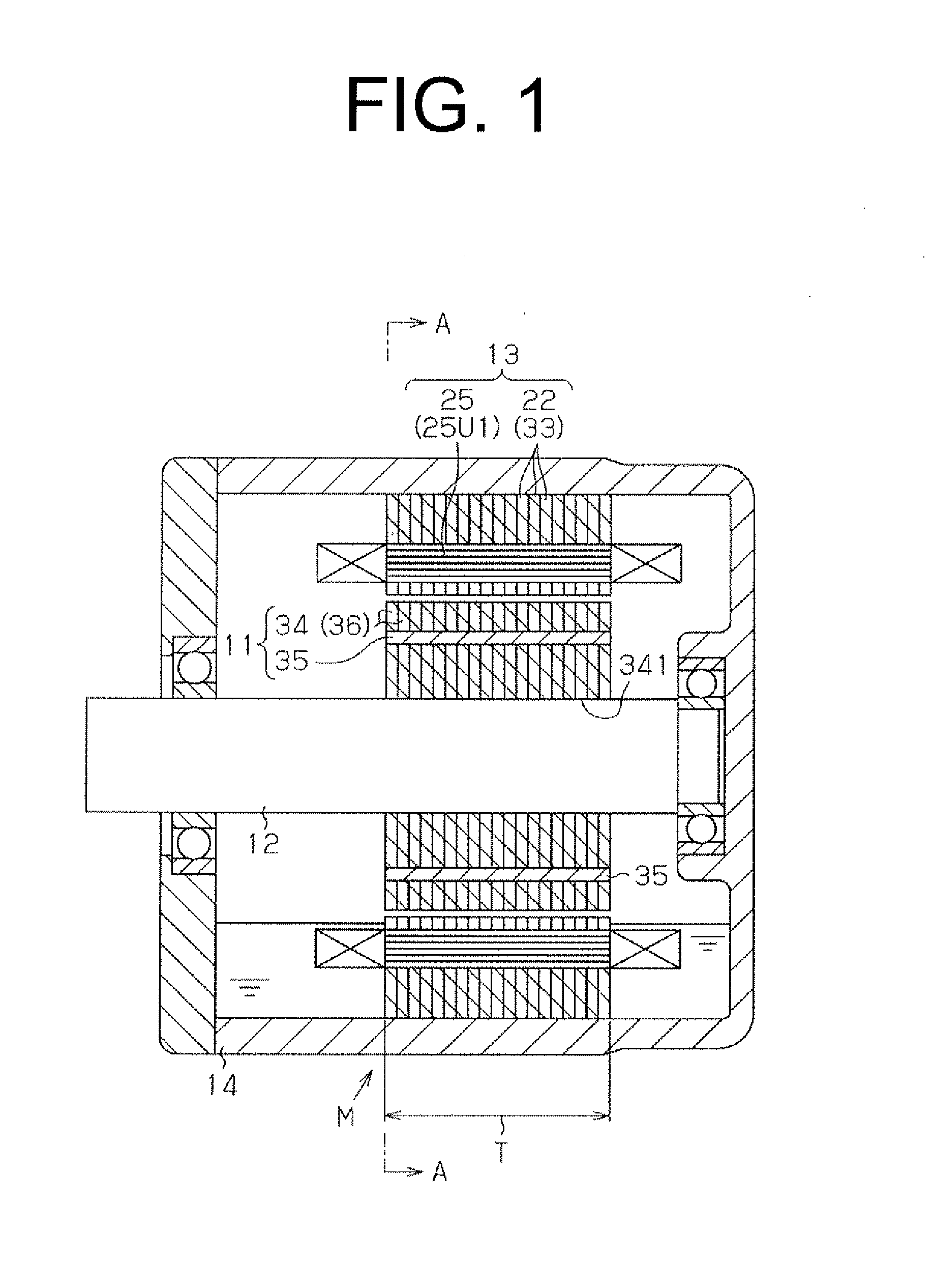
[0023]The following will describe the rotary electric machine according to the embodiment of the present invention with reference to FIGS. 1 through 5B. Referring to FIG. 1 showing the rotary electric machine in longitudinal sectional view, the rotary electric machine is designated by reference symbol M and includes a rotor 11, a rotary shaft 12, a stator 13 and a motor housing 14. The rotor 11 is fixedly mounted on the rotary shaft 12 and the stator 13 is fixedly mounted to the inner peripheral surface of the motor housing 14. Oil for cooling the stator 13 is sealed in the motor housing 14 to such a level that any part of the rotor 11 is not immersed in the oil.

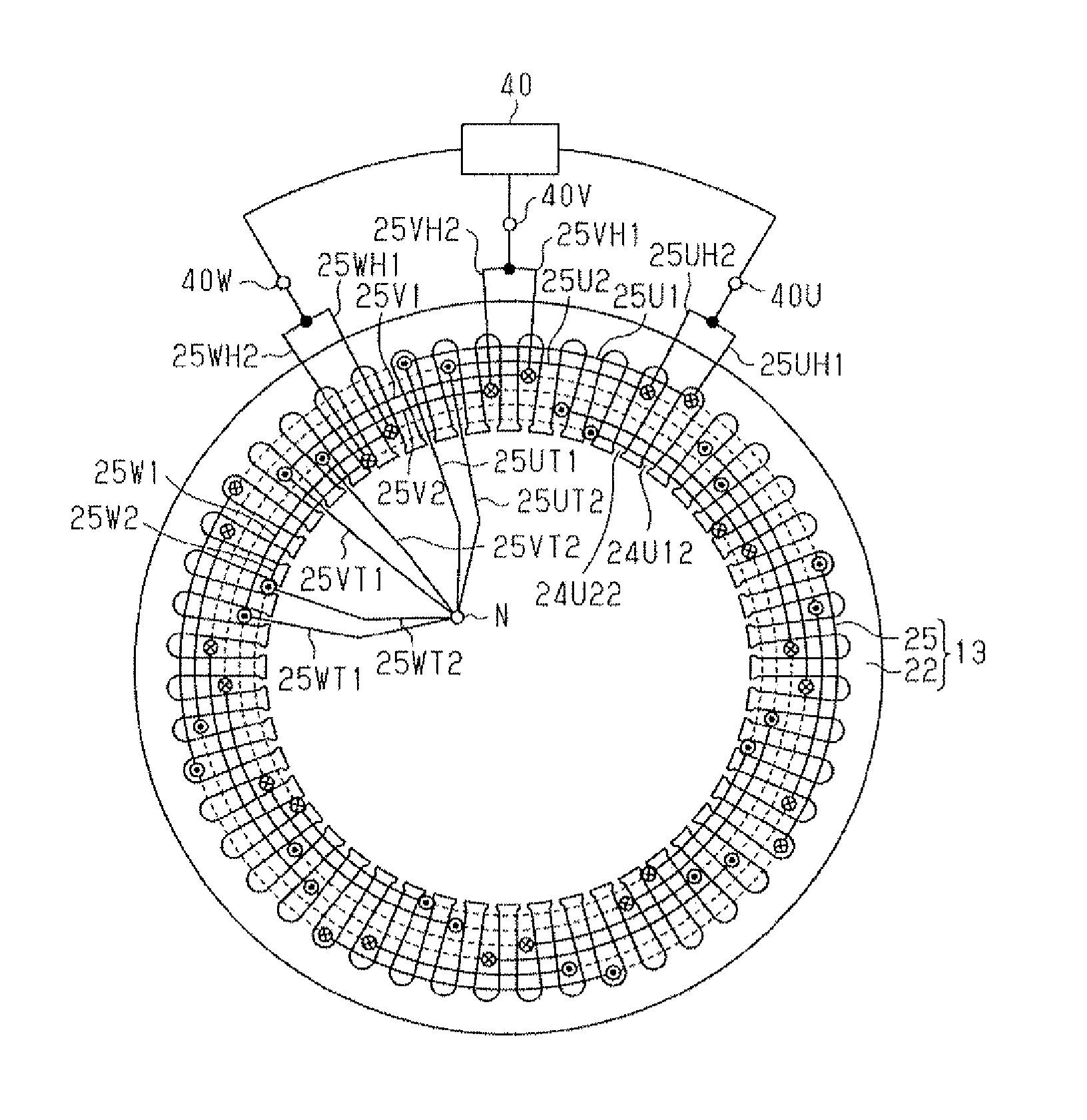
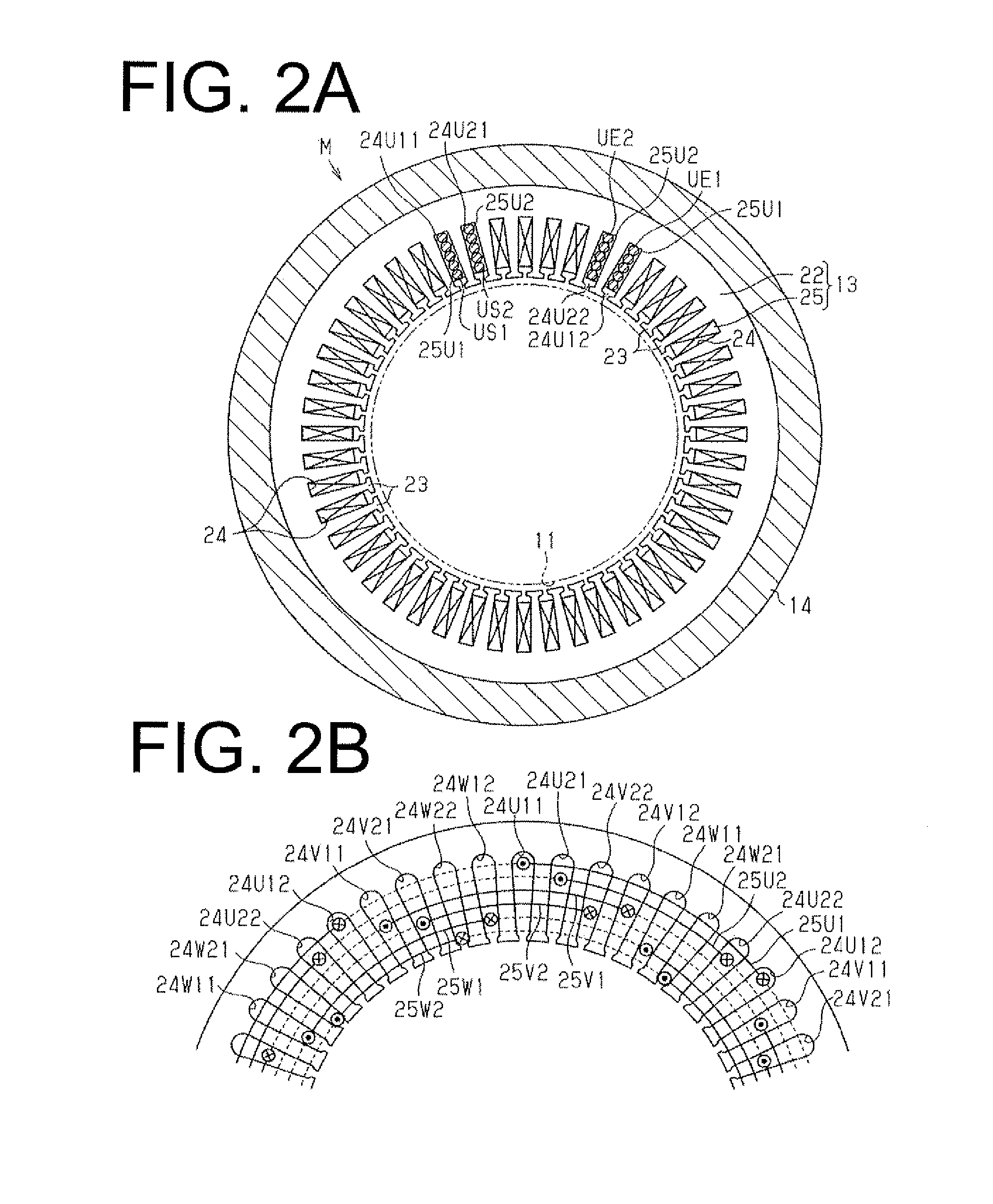
[0024]As shown in FIG. 2A, the stator 13 includes an annular stator core 22 having on the inner periphery thereof a plurality of teeth 23 that define a plurality of slots 24 between the teeth 23, and coils 25 inserted in the slots 24. The stator 13 has three phases, eight poles and 48 slots 24. In the following description, ...


PUM


Abstract

A stator of a rotary electric machine includes a stator core and polyphase coils. The stator core has a plurality of slots. The polyphase coils are provided in the slots. Each phase of the polyphase coils has a plurality of coils formed for each pole and connected in parallel. When winding in which a coil pitch is equal to number of slots divided by number of poles is termed full-pitch winding, when winding in which a coil pitch is larger than the coil pitch of the full-pitch winding is termed long-pitch winding, and when winding in which a coil pitch is smaller than the coil pitch of the full-pitch winding is termed short-pitch winding, at least two of the coils of each phase are formed on the stator core by wave winding to alternate between the long-pitch winding and the short-pitch winding along a circumferential direction of the stator core.

Description

BACKGROUND OF THE INVENTION[0001]The present invention relates to a stator of a rotary electric machine with a plurality of poles, the stator including a stator core and polyphase coils, the stator core having teeth that define therebetween a plurality of slots, the polyphase coils being provided in the slots, each phase of the polyphase coils having a plurality of coils that are formed for each pole and connected in parallel.[0002]In some rotary electric machines, the rotor and the stator are disposed eccentrically with respect to each other. In the stator wherein coils are connected in parallel, imbalance of electromotive force caused by the eccentricity may generate cyclic current in the parallel circuit thereby to cause an increase of noise and of vibration of the rotary electric machine during the operation. In order to reduce the cyclic current, Japanese Unexamined Patent Application Publication No. 2006-311716 discloses a winding structure of a rotary electric machine.[0003]T...

Claims


Application Information

Patent Timeline
IPC IPC(8): H02K3/28
CPCH02K3/28H02K23/32H02K3/12
Inventor MINOSHIMA, NORIMOTOSAIJO, MASAKI
Owner TOYOTA IND CORP
Why Eureka
Try Eureka