Armature and motor including armature
- Summary
- Abstract
- Description
- Claims
- Application Information
AI Technical Summary
Benefits of technology
Problems solved by technology
Method used
Image
Examples
second preferred embodiment
[0064]FIG. 8 shows the insulator 17 (referred to as an “insulator 17A”) of a second preferred embodiment of the present invention. Moreover, since the basic configurations are similar to those of the first preferred embodiment, the similar configurations are denoted with the same reference numbers and explanations thereof are omitted.
[0065]The insulator 17A preferably further improves the space factor. Specifically, a plurality of guide ribs 52 is preferably disposed on each of both corners 51 and 51 of the first member 211 to which the first end wall 221 and the first side walls 231 are extended. The guide ribs 52 have a cross-sectional shape which spreads out from the tip side toward the base end side in the first member 211. Moreover, the guide ribs 52 are preferably disposed at the same or substantially the same interval as the interval in which the conducting wire is arranged in the radial direction over the entire region in radial direction of the corner 51. Since the portions...
third preferred embodiment
[0067]FIG. 9 shows the insulator 17 (referred to as an “insulator 17B”) of a third preferred embodiment of the present invention. Moreover, since the basic configurations are similar to those of the second preferred embodiment or the like, the similar configurations are denoted with the same reference numbers and explanations thereof are omitted.
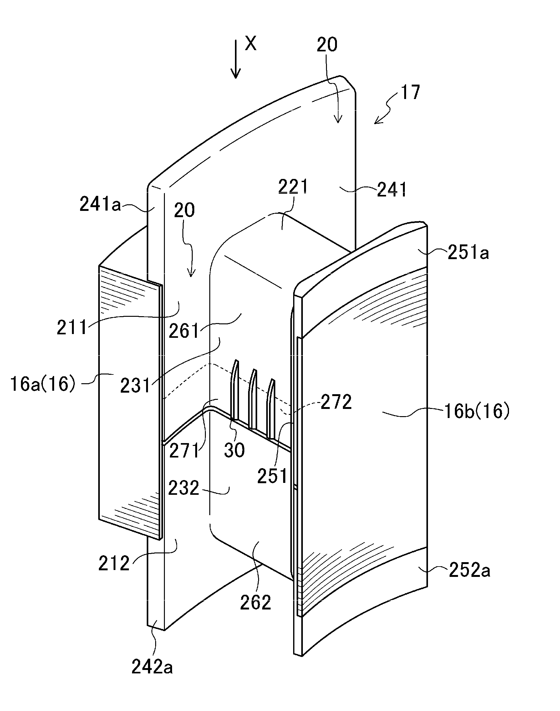
[0068]The insulator 17B is preferably arranged to further improve the space factor. Specifically, ribs 30 are disposed at the same or substantially the same interval as the interval in which the conducting wire 18a is arranged in the radial direction over the approximately entire region in radial direction of the first overlap portion 271 (first side wall 231). In addition, the disposition of the ribs 30 corresponds to the disposition of the guide ribs 52. That is, the guide ribs 52 are preferably disposed on the extended lines of the ribs 30.
[0069]Specifically, as shown in FIG. 10, similarly to the guide ribs 52, a height D of the rib 30 fr...
fourth preferred embodiment
[0071]FIGS. 11 and 12 show the insulator 17 (referred to as an “insulator 17C”) of a fourth preferred embodiment of the present invention. Moreover, since the basic configurations are similar to those of the third preferred embodiment, the similar configurations are denoted with the same reference numbers and explanations thereof are omitted.
[0072]In the insulator 17C, connection ribs 61 are preferably disposed between the ribs 30 and the guide ribs 52 so as to be extended to both. In addition, the ribs 30 and the connection ribs 61 have the same cross-sectional shape as each other. Therefore, the ribs 30, the guide ribs 52, and the connection ribs 61 are defined to be connected and integrated as a single monolithic member.
[0073]Specifically, similarly to the shape of the guide ribs 52, the ribs 30 or the connection ribs 61 have a cross-sectional shape which spreads out from the tip side toward the base end side in the ribs 30 or the connection ribs 61 and are protruded from the fir...
PUM
 Abstract
Description
Claims
Application Information
 - R&D
- Intellectual Property
- Life Sciences
- Materials
- Tech Scout
- Unparalleled Data Quality
- Higher Quality Content
- 60% Fewer Hallucinations
Browse by: Latest US Patents, China's latest patents, Technical Efficacy Thesaurus, Application Domain, Technology Topic, Popular Technical Reports.
© 2025 PatSnap. All rights reserved.Legal|Privacy policy|Modern Slavery Act Transparency Statement|Sitemap|About US| Contact US: help@patsnap.com


