
Thermal receptacle with phase change material

a technology of phase change material and thermal receptacle, which is applied in the direction of indirect heat exchanger, lighting and heating apparatus, domestic cooling apparatus, etc., can solve the problems of reducing the temperature of hot beverages, burning to the mouth, and skin burns,

Inactive Publication Date: 2013-08-29
KOLOWICH J BRUCE +1
View PDF7 Cites 111 Cited by
  • Summary
  • Abstract
  • Description
  • Claims
  • Application Information

AI Technical Summary

Benefits of technology

The invention is a liquid receptacle that can quickly lower the temperature of a liquid to a warm range and maintain it for an extended period of time. The receptacle has a phase change material inside it that absorbs and releases thermal energy from the liquid to regulate the temperature. The receptacle has an insulation layer and an outer shell with a vacuum or insulating material between them. The receptacle can be made using a blow molding or plastic forming process. The invention also includes an accessory for use with an insulated cup to provide the benefits of a phase change material.

Problems solved by technology

Some impatient consumers will attempt to drink the beverage too soon resulting in burns to the mouth.
Similarly, if the drink is spilled before it has had sufficient time to cool, burns to the skin may result.
This approach rapidly cools the beverage but dilutes the hot beverage.
This is frequently undesirable.
This approach is often inconvenient and imprecise; if the person adds too little or too much, the temperature of the hot beverage will be higher or lower than desired and may require further attention.
Finally, this approach does not provide any assistance in maintaining the temperature of the hot beverage in the acceptable drinking temperature range.
Once the beverage reaches an acceptable temperature, it will continue to lose thermal energy to its surroundings.
This results in the beverage becoming cool too quickly.
This approach suffers from some of the same limitations as adding cool liquid or ice.
If the cup is too cool or too warm or has too much or too little thermal mass, the beverage will stabilize at the wrong temperature.
Also, while a heavy container will slow the rate of cooling somewhat due to the increase in the total thermal mass of the system, the effect will be small and the beverage will only remain in the ideal drinking range for a short period.
These approaches slow the cooling rate of the beverage.
However, the ability of the insulated mugs currently on the market to maintain beverage temperatures is relatively limited.
Stainless, vacuum insulated mugs are best at maintaining temperature, but no product currently exists which can passively cool a hot beverage quickly.
Insulation does not provide a way to add thermal energy back to the beverage.
All of theses approaches suffer from lack of portability and dependence on outside energy sources.
They also fail to address the need to rapidly cool a beverage to an acceptable drinking temperature range.
Also, if the infant is fussy and does not drink the entire contents of the bottle immediately, the contents may cool to the point that the infant will not drink it.
Insulated baby bottles are available which extend the time the contents are acceptably warm but they fail to add thermal energy back to the bottle contents.
If the water is too hot, the person may be unable to enter the water or may be injured by it.
If a person wishes to soak or a child wishes to play in the tub for a period of time, the water may become uncomfortable due to its falling temperature.
Insulated bathing tubs are available which help reduce the rate of temperature loss but do not address the issue of water that is too hot.
They also fail to add thermal energy back into the tub.
Some whirlpool tubs include heaters for maintaining the temperature of the water but these devices are expensive to purchase and operate, require a complex system of pumps, valves and switches, and are noisy in operation.
They also fail to address the issue of water that is too hot.

Method used


Image

  • Thermal receptacle with phase change material
  • Thermal receptacle with phase change material
  • Thermal receptacle with phase change material

Examples


Embodiment Construction

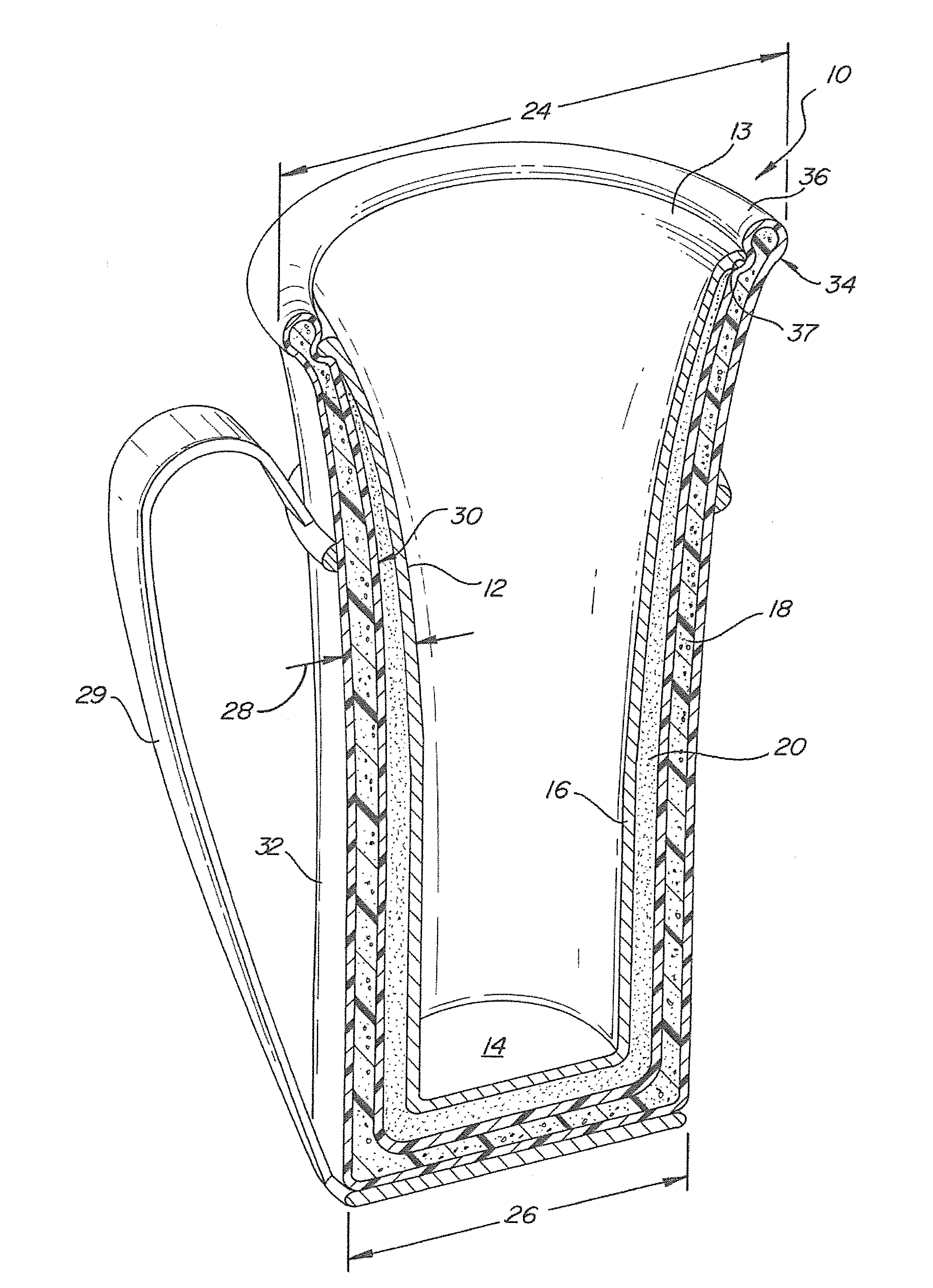
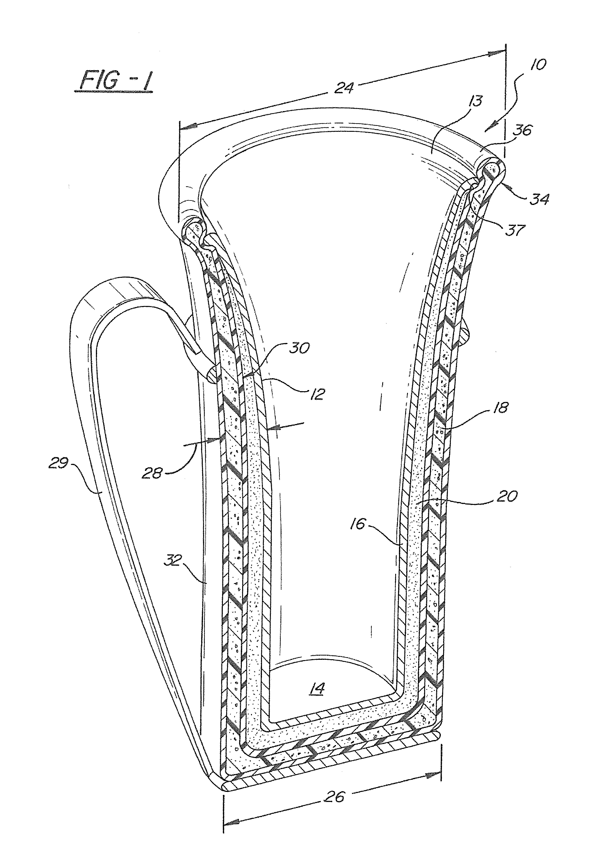
[0049]Referring to the Figures, wherein like numerals indicate like or corresponding parts throughout the several views, a liquid receptacle is generally indicated at 10. The receptacle 10 includes a inner vessel 12 with an open upper end 13 and a closed lower end 14 and a wall 16 connecting the upper 13 and lower 14 ends. An insulated outer shell 18 is spaced from the inner vessel 12 defining an interstitial chamber 20 therebetween. Phase change material is disposed within the chamber 20.

[0050]Preferably, the inner vessel 12 is either wholly or partially formed of a material having a high thermal conductivity such as aluminum, copper or alloys thereof. Pure aluminum has a thermal conductivity of 237 Watts / meter-degree Kelvin when measured at 300 degrees Kelvin. Most aluminum alloys have a thermal conductivity above 150 Watts / meter-degree Kelvin. Pure copper has a thermal conductivity of 401 Watts / meter-degree Kelvin. Most alloys of copper have thermal conductivities significantly l...


PUM


Abstract

A liquid receptacle for rapidly lowering the temperature of a liquid contained therein to a warm range suitable for human contact and maintaining the liquid in the warm range for an extended period of time includes an inner vessel with an open upper end and a closed lower end and a wall connecting the upper and lower end. An insulated outer shell is spaced from the inner vessel to define an interstitial chamber between the inner vessel and the outer shell. A phase change material occupies the chamber and regeneratively absorbs thermal energy from the liquid to cool the liquid and then releases the thermal energy back to the liquid to maintain the temperature of the liquid.

Description

CROSS-REFERENCE TO RELATED APPLICATIONS[0001]This Application is a Continuation-in-Part of U.S. patent application Ser. No. 13 / 099,888, filed May 3, 2011, which is a Continuation of application Ser. No. 11 / 452,569 filed on Jun. 14, 2006, now U.S. Pat. No. 7,934,537, issued May 3, 2011. Application Ser. No. 11 / 452,569 is a Continuation of application Ser. No. 11 / 258,703 filed on Oct. 26, 2005, now U.S. Pat. No. 7,059,387. Application Ser. No. 11 / 258,703 is a Continuation of application Ser. No. 10 / 690,098 filed on Oct. 21, 2003, now U.S. Pat. No. 6,968,888. Application Ser. No. 10 / 690,098 is a Continuation of application Ser. No. 09 / 055,377 filed on Apr. 6, 1998, now U.S. Pat. No. 6,634,417. Application Ser. No. 09 / 055,377 claims the benefit of U.S. Provisional Application 60 / 043,431 filed on Apr. 7, 1997. Each patent application identified above is incorporated herein by reference in its entirety to provide continuity of disclosure.TECHNICAL FIELD[0002]The subject invention relates ...

Claims


Application Information

Patent Timeline
Patent Type & Authority Applications(United States)
IPC IPC(8): B65D81/38
CPCY02E60/145Y02E60/147A47J36/2416A47J36/2444A47J41/0044A47G19/127B65D81/3844C09K5/063F28D20/02F28D2020/0008Y10S165/902B65D81/3872A47J43/0794A47G19/2288Y02E60/14A47G19/2266A61J9/00B65D81/3869B65D81/3874
Inventor KOLOWICH, J. BRUCEBOOSKA, RAYMOND
Owner KOLOWICH J BRUCE
Learn More