Cardiac stimulator for cardiac contractility modulation

a cardiac contractility and stimulator technology, applied in the field of cardiac contractility modulation stimulators, can solve the problems of high mortality, low ejection fraction (ef), high contractility, etc., and achieve the effect of eliminating a potentially proarrhythmic effect and lowering the proarrhythmic risk of ccm stimulation

Inactive Publication Date: 2013-08-22
BIOTRONIK SE & CO KG
View PDF2 Cites 8 Cited by
  • Summary
  • Abstract
  • Description
  • Claims
  • Application Information

AI Technical Summary

Benefits of technology

The patent describes a cardiac stimulator that reduces the risk of potentially life-threatening arrhythmias when combining three types of therapy: cardiac contractility modulation, antibradycardia, and cardiac resynchronization therapy. The device can automatically optimize the therapy and adjust its parameters to maximize heart function. This approach reduces the risk of complications and improves the effectiveness of cardiac therapy.

Problems solved by technology

In healthy people, the inotropy of the heart thus causes a rise in the contractility due to increased physiological demand.
This is accompanied by a low ejection fraction (EF) as well as by a low quality of life and high mortality.
With the aforementioned method of CCM synchronization, sensing errors can cause the CCM pulses to be delivered even outside the absolute refractory period.
This risk is increased especially when using CCM stimulation together with additional stimulators, such as a biventricular pacemaker or defibrillator, because delivery of subthreshold stimuli can be sensed via the CCM system, which could trigger delivery of a CCM pulse.
A further disadvantage of the CCM therapy consists in the necessity to implant two additional stimulation electrodes at the ventricular septum.

Method used


Image

  • Cardiac stimulator for cardiac contractility modulation
  • Cardiac stimulator for cardiac contractility modulation
  • Cardiac stimulator for cardiac contractility modulation

Examples


Embodiment Construction

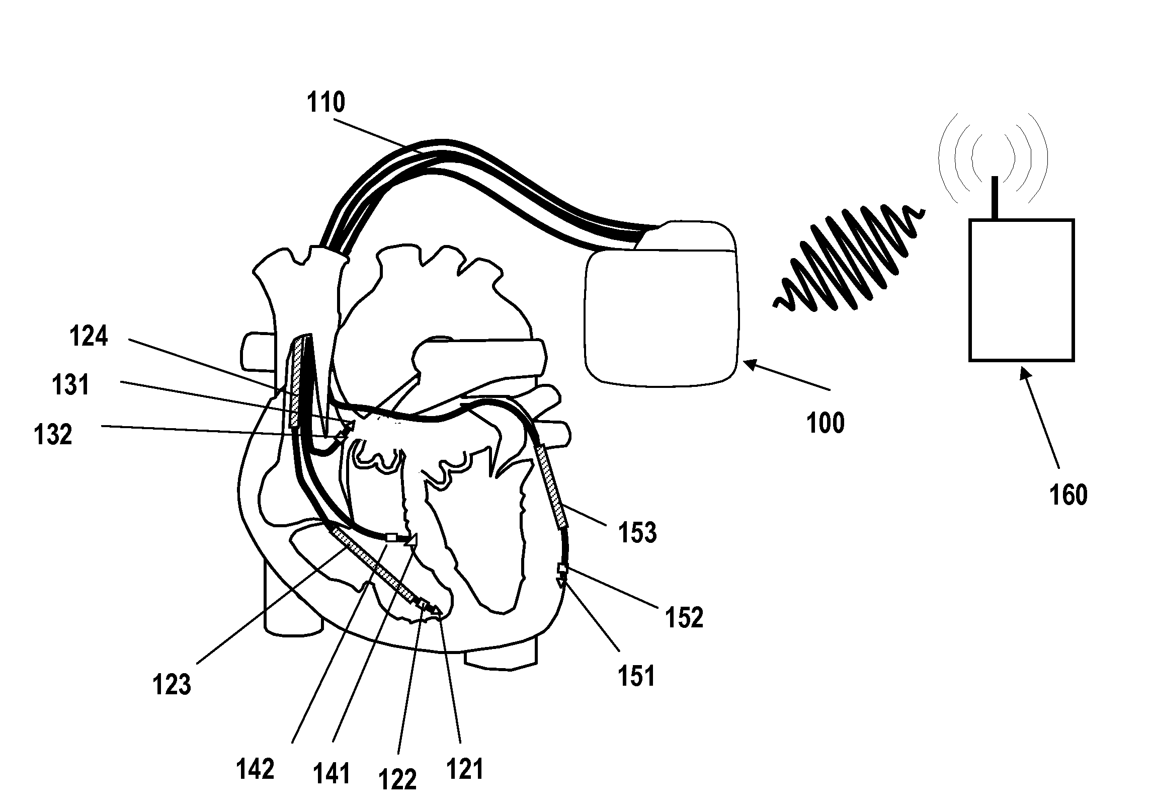
[0072]FIG. 1 shows a cardiac stimulator of a triple-chamber ICD system with integrated CRT-CCM function as an implementation example. A generator 100 is connected to several implantable electrode leads 110. For the purpose of right-ventricular sensing and stimulation, a right-ventricular electrode lead comprises a right-ventricular tip electrode 121 and a right-ventricular ring electrode 122 at the distal end of the right-ventricular electrode lead. In the case of a cardiac resynchronization therapy (CRT), right-ventricular stimulation pulses for the biventricular CRT stimulation are delivered via the right-ventricular tip electrode 121. A distal shock coil 123, and optionally a proximal shock coil 124, is arranged on the right-ventricular electrode lead for delivering defibrillation shocks. The generator housing 100 forms the counter-electrode for the delivery of defibrillation shocks.

[0073]At the distal end, a right-atrial electrode lead has a bipolar sensing and stimulation pole ...


PUM


Abstract

At least one embodiment of the invention relates to a cardiac stimulator comprising at least one stimulation unit to deliver subthreshold stimulation pulses for a cardiac contractility modulation therapy via at least two stimulation electrode poles, and at least one sensing unit to detect cardiac electrical or mechanical actions. The at least one sensing unit detects signals characteristic of cardiac action and comprises, or is connected to, an evaluation unit that evaluates signals detected by the sensing unit and supplies a corresponding evaluation result signal. The cardiac stimulator further comprises a therapy control unit to control a respective cardiac contractility modulation therapy depending on a respective evaluation result signal. A respective cardiac contractility modulation therapy is activated / deactivated depending on a stimulation success / failure of a suprathreshold stimulation, and / or therapy parameters of a respective cardiac contractility modulation therapy are selected and / or adjusted depending on the respective evaluation result signal.

Description

[0001]This application claims the benefit of U.S. Provisional Patent Application 61 / 599,432 filed on 16 Feb. 2012, the specification of which is hereby incorporated herein by reference.BACKGROUND OF THE INVENTION[0002]1. Field of the Invention[0003]At least one embodiment of the invention relates to a cardiac stimulator comprising at least one stimulation unit, at least three stimulation electrode poles and at least one electrode lead. The at least one stimulation unit is connected or to be connected to the at least three stimulation electrode poles via the at least one electrode lead and is configured to deliver subthreshold stimulation pulses for a cardiac contractility modulation (CCM) therapy via the at least two stimulation electrode poles.[0004]2. Description of the Related Art[0005]Implantable cardiac stimulators in the form of cardiac pacemakers or cardioverters / defibrillators are common in the field of art. Such cardiac stimulators are generally connected to electrode leads...

Claims


Application Information

Patent Timeline
IPC IPC(8): A61N1/365
CPCA61N1/368A61N1/365
Inventor DOERR, THOMAS
Owner BIOTRONIK SE & CO KG
Why Eureka
Try Eureka