Broadband electromagnetic band-gap (EBG) structure

Active Publication Date: 2013-08-22
UNITED STATES OF AMERICA THE AS REPRESENTED BY THE SEC OF THE ARMY
View PDF8 Cites 25 Cited by
  • Summary
  • Abstract
  • Description
  • Claims
  • Application Information

AI Technical Summary

Benefits of technology

The patent describes methods and apparatus for creating a structure that blocks certain electromagnetic frequencies. This is done by using patterns of cells that resonate at different frequencies. The patterns are arranged in a way that their resonance progresses from one pattern to another, creating a continuous wide range of frequencies that can be blocked. This arrangement can be provided in a single level or on different levels. The technical effect is a better ability to block certain frequencies of electromagnetic energy.

Problems solved by technology

The reflection phase is important when EBG structures are used for designing an antenna because of the known consequence that the efficiency of the antenna is affected by destructive interference of the wave reflected from the ground plane with the wave directly radiated from the antenna.
Although EBG structures have been known in microwave design for more than two decades and are known to provide advantages due to their compact size and low loss when integrated into an antenna design, EBG structures typically work over a narrow frequency band, which makes them not practical for use with broadband antennas.

Method used


Image

  • Broadband electromagnetic band-gap (EBG) structure
  • Broadband electromagnetic band-gap (EBG) structure
  • Broadband electromagnetic band-gap (EBG) structure

Examples


Embodiment Construction

[0019]The present invention describes embodiments for a broadband electromagnetic bandgap (EBG) structure and use of that structure in an antenna application, The invention derives from a progressive cascade of patterns of EBG structures, each pattern having a progressively increasing resonant frequency, so that the combined effect of the cascade structure provides a continuous ultra-wide broadband phase response, The new structure is validated by using it in combination with a broadband antenna and comparing the performance of the antenna with a uniform EBG ground plan structure and then with a broadband EBG ground plane structure having a progressive cascade of patterns as described herein.

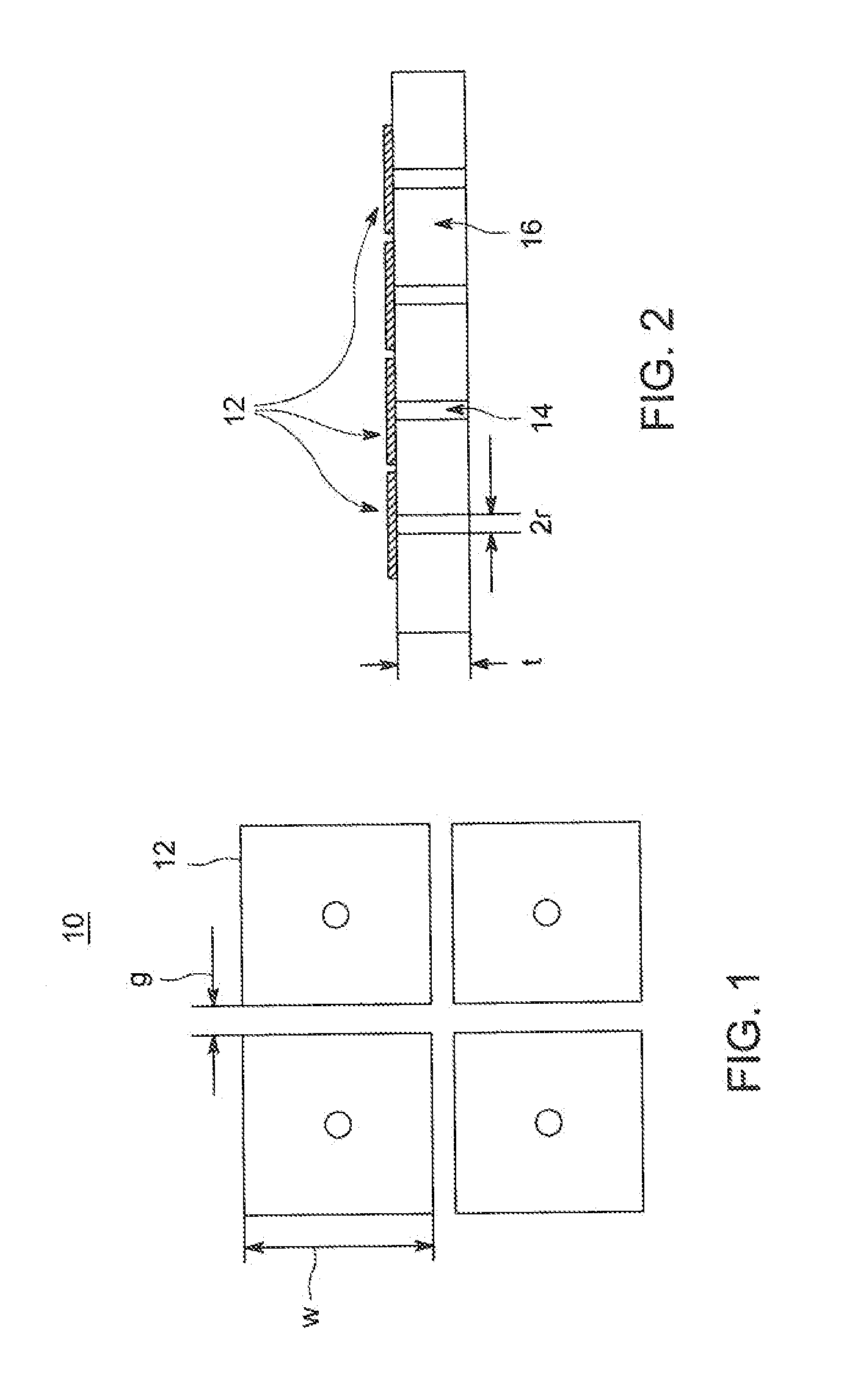
[0020]Mushroom-like EBG structures have parallel LC resonators, such as shown in FIGS. 1 and 2 which illustrate top and side views, respectively of a 2×2 patch mushroom EBG structure 10 of a type useful for forming some embodiments of the invention. The structure includes a periodic conductive p...


PUM


Abstract

An electromagnetic bandgap structure comprising a progressive cascade of a plurality of patterns of cells. The cells of each pattern are dimensioned so that each pattern has a reflection phase response centered at a different, but closely-spaced, frequency compared with the reflection phase response of an adjacently positioned pattern, so that the combined reflection phase response of the plurality of patterns provides a continuous wideband operational range.

Description

CROSS REFERENCE TO RELATED APPLICATIONS[0001]This application claims benefit of U.S. provisional patent application Ser. No. 61 / 601,584, filed Feb. 22, 2012, which is herein incorporated by reference.GOVERNMENT INTEREST[0002]The invention described herein may be manufactured, used and licensed by or for the U.S. Government.”FIELD OF INVENTION[0003]Embodiments of the present invention generally relate to electromagnetic band-gap (EBG) structures, and more particularly to EBG structures having a progressive cascade of patterns of EBG cells, which progressive cascade of patterns result in a continuous wideband operational phase response for the EBG structures, as well as antennas using such wideband EBG structures.BACKGROUND OF THE INVENTION[0004]Electromagnetic band gap (EBG) structures are periodic structures that have special properties, such as high surface impedance. Accordingly, a ground plane having EBG structures formed thereon can act as a close-to-perfect magnetic conducting ...

Claims


Application Information

Patent Timeline
IPC IPC(8): H01Q19/10H01Q15/14
CPCH01Q19/10H01Q15/008H01Q15/14H01Q19/108
Inventor ZAGHLOUL, AMIR I.WEISS, STEVEN J.
Owner UNITED STATES OF AMERICA THE AS REPRESENTED BY THE SEC OF THE ARMY
Why Eureka
Try Eureka