
Hair dryer

a hair dryer and dryer technology, applied in the field of hair dryers, can solve the problems of insufficient degree of attainment, achieve the effects of reducing water volume, cleaving/shortening the polymerization of water clusters, and drying and blow-drying hair in a short amount of tim

Inactive Publication Date: 2013-08-22
CREATE
View PDF4 Cites 6 Cited by
  • Summary
  • Abstract
  • Description
  • Claims
  • Application Information

AI Technical Summary

Benefits of technology

The present invention relates to a hair dryer that is designed to provide effective care for hair and scalp by utilizing far-infrared rays and electromagnetic waves emitted from a ceramics coated layer. The hair dryer includes an air-rectifying member, such as a diffuser or an air-rectifying plate, which prevents the air flow from being diffused when blown out through the air outlet. The ceramics coated layer is applied on the surface of the air-rectifying member to ensure that the effects of the far-infrared rays and electromagnetic waves are spread onto almost the entire portion of the air flow to increase the sensation of moisture and gloss on the hair. The ceramics coated layer is formed by coating a mixed powder of far-infrared ray powder and multi-element mineral powder. The hair dryer can also include a blowing-out nozzle or an intermediate nozzle to further enhance the spreading of the effects of the ceramics coated layer.

Problems solved by technology

However, because the ceramics coated layer is provided on the inner surface of the air passage, the air is not in contact with the ceramics coated layer to a sufficient degree in the central portion of the air flow, and thus the desired effects are not obtained to a sufficient degree, which has been problematic.

Method used


Image

  • Hair dryer
  • Hair dryer
  • Hair dryer

Examples


working example 1

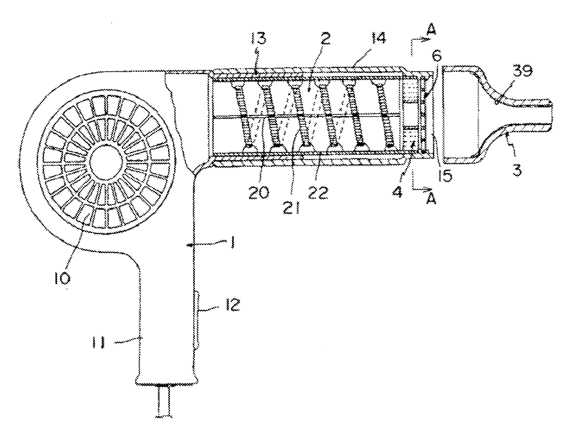
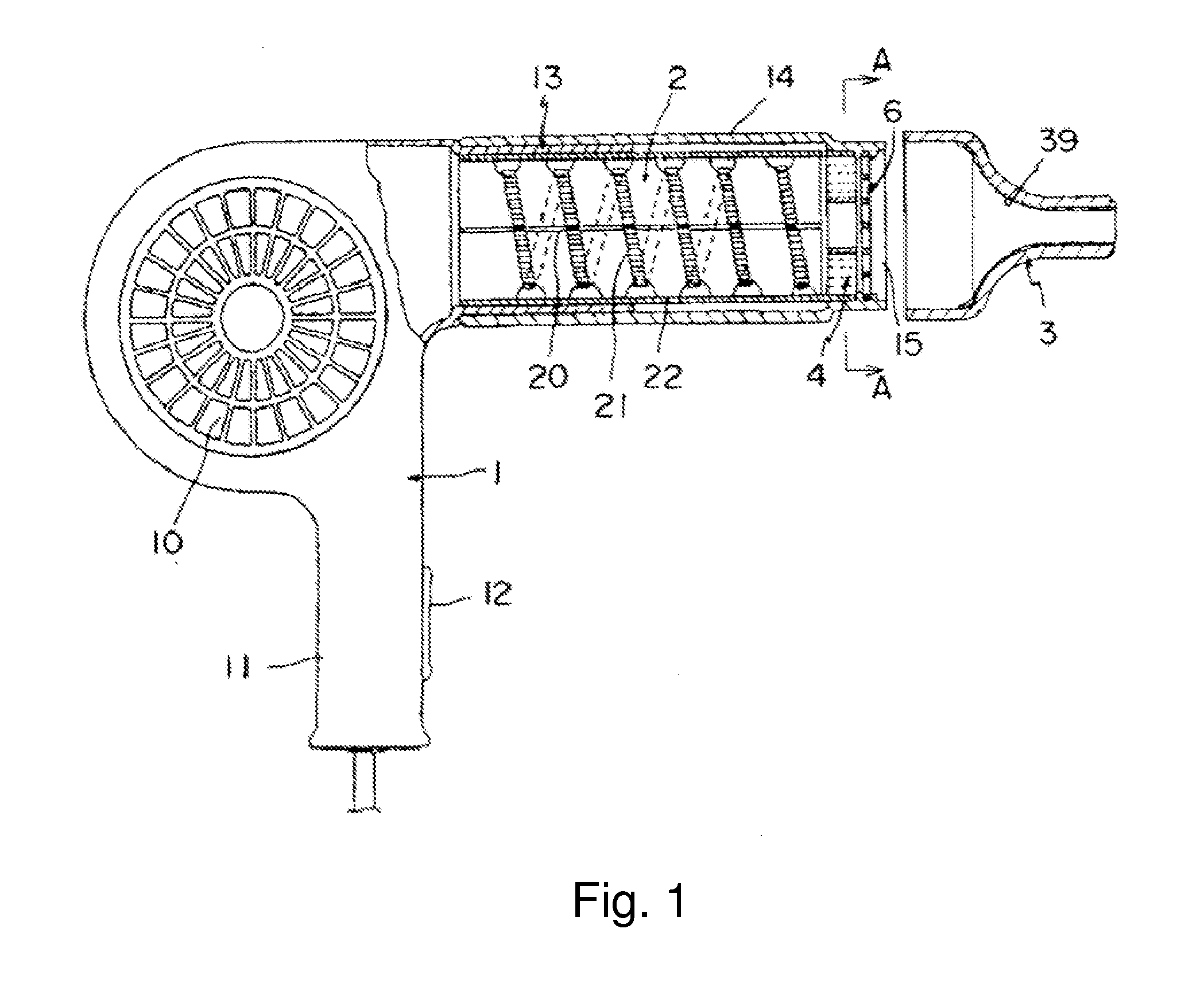
[0024]The hair dryer shown in FIG. 1 primarily comprises body 1, heater 2, and blowing-out nozzle 3. This hair dryer is constituted with a heat-resistant plastic material.

[0025]Body 1 stated above is equipped with a fan (not shown in the figures) therein, and air inlet 10 is provided on both sides of the fan. Moreover, handle 11 is provided on body 1 so that the user is able to hold the hair dryer with their hand. On handle 11, toggle switch 12 for toggling between hot air and cold air or for changing the amount of air, temperature, and the like is provided.

[0026]On body 1, connecting cylinder 13 is formed; on the outer circumference of connecting cylinder 13, blowing-out cylinder 14 is inserted, and the tip of blowing-out cylinder 14 is formed into air outlet 15.

[0027]Heater 2 stated above heats the air sent by the fan, and is formed in the following manner: mica plate 20 is formed into a cross shape; on the outer circumference of mica plate 20, e wire 21 is wound around, and the a...

working example 2

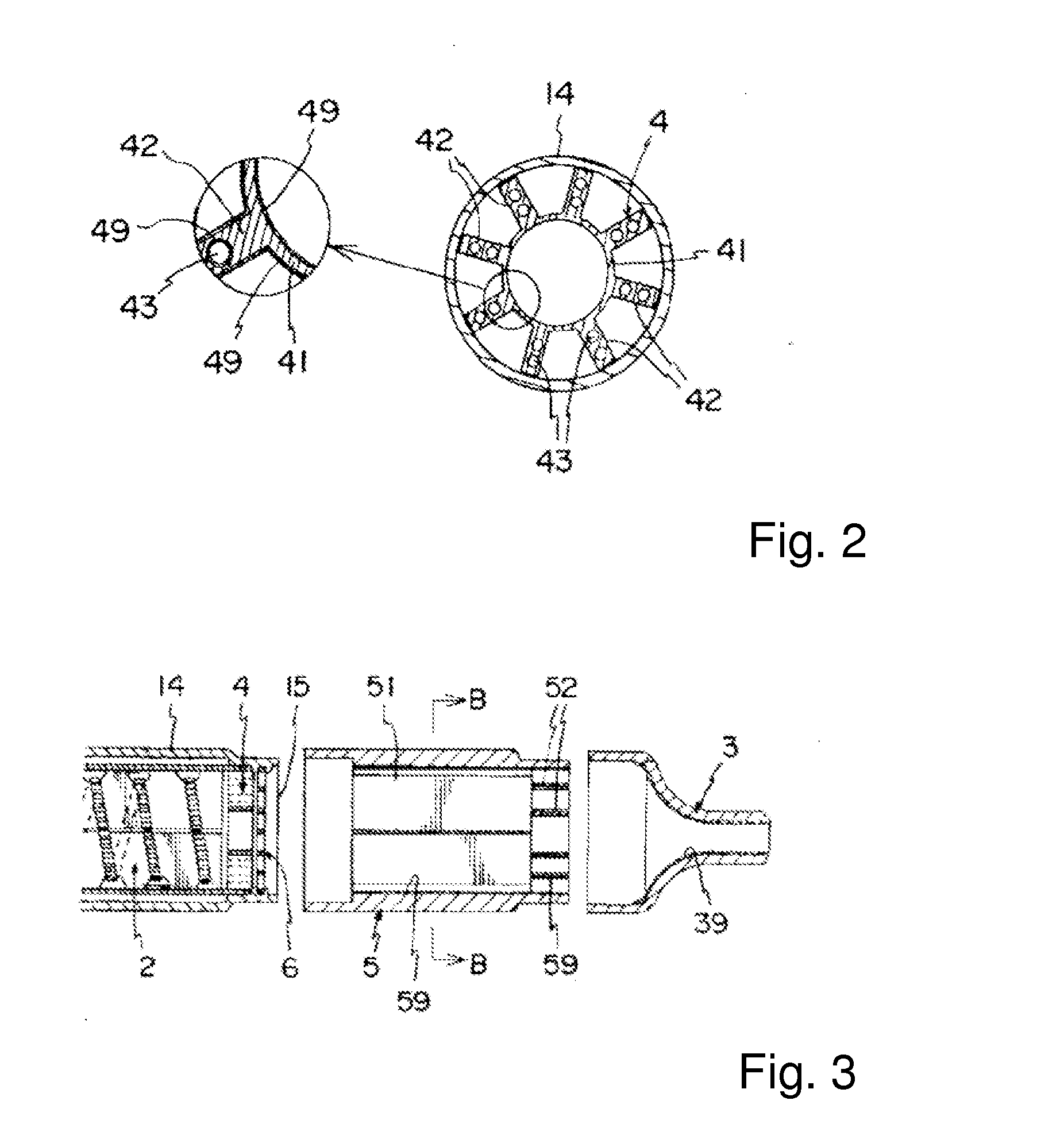
[0037]Working Example 2 shown in FIG. 3 is an example in which intermediate nozzle 5 is provided between air outlet 15 and blowing-out nozzle 3 in a freely mountable / dismountable manner.

[0038]Intermediate nozzle 5 is mounted in a freely mountable / dismountable manner so that the inner circumference of the base of intermediate nozzle 5 is engaged with the outer circumference of the tip of blowing-out cylinder 14, and the inner circumference of the base of blowing-out nozzle 3 is engaged with the outer circumference of the tip of intermediate nozzle 5; air rectifying members are provided within intermediate nozzle 5. As shown in FIG. 4, the air rectifying members are formed by air rectifying plates 51, which evenly partition the inside of intermediate nozzle 5 into 6 parts in the circumferential direction (the plates do not completely partition the space, leaving the space partially linked) as well as double-circular KURIRU [sic; grill] frame 52, which is provided on the inner portion ...


PUM


Abstract

The purpose of the present device is to provide a hair dryer that is capable of spreading the effects of far-infrared rays and the effects of electromagnetic waves onto almost the entire portion of the air flow to increase the sensation of moisture and gloss on the hair, and that is consequently capable of rendering the resulting hair moist, smooth, and easy-to-care for.

Description

MEANS FOR SOLVING THE PROBLEM [0001]Hair dryer comprising an air-rectifying member such as diffuser (4), which is provided on air outlet (15); wherein a ceramics coated layer, which is formed by coating a mixed powder formed by far-infrared ray powder and multi-element mineral powder, is provided on the surface of the air-rectifying member.DETAILED EXPLANATION OF THE DEVICE[0002]1. Industrial Field of Application[0003]The present device relates to a hair dryer that is utilized to dry or blow-set hair, and particularly to a hair dryer that is capable of providing effective care for hair and scalp by utilizing far-infrared rays emitted from far-infrared ray emitting powder and electromagnetic waves (weak energy) emitted from multi-element mineral powder.[0004]2. Background Technologies[0005]When utilizing a hair dryer, it generally takes a long time to dry or blow-set hair by causing hot air or cold air to be blown from the blower onto the hair. In particular, when utilizing a hair dr...

Claims


Application Information

Patent Timeline
IPC IPC(8): A45D20/08
CPCA45D2200/205A45D20/12A45D20/122
Inventor KAIZUKA, KAZUTOSHI
Owner CREATE
Learn More