Solar Assembly Structure

a technology of solar energy and assembly structure, applied in the direction of heat collector mounting/support, manufacturing tools, light and heating equipment, etc., can solve the problems affecting the efficiency of a concentrating system

Inactive Publication Date: 2013-08-15
SOLFOCUS
View PDF0 Cites 14 Cited by
  • Summary
  • Abstract
  • Description
  • Claims
  • Application Information

AI Technical Summary

Benefits of technology

[0004]A solar concentrator assembly includes a pair of rails coupled together only by one or more backpans which are mounted between the pair of rails. The rails are configured to resist a portion of cantilever deflection along the length of the rails. The backpans seat solar concentrator arrays and are configured to provide torsional rigidity and deflection resistance in at least one direction orthogonal to the cantilever deflection.

Problems solved by technology

Misalignment of the optical components in a solar concentrator can affect the efficiency of a concentrating system.

Method used


Image

  • Solar Assembly Structure
  • Solar Assembly Structure
  • Solar Assembly Structure

Examples


Embodiment Construction

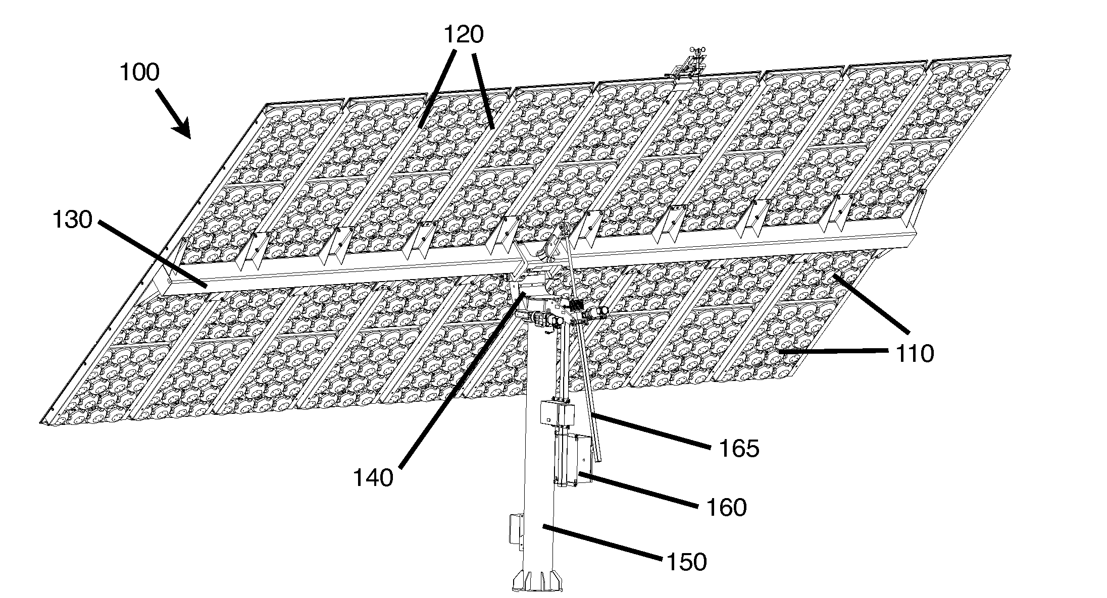
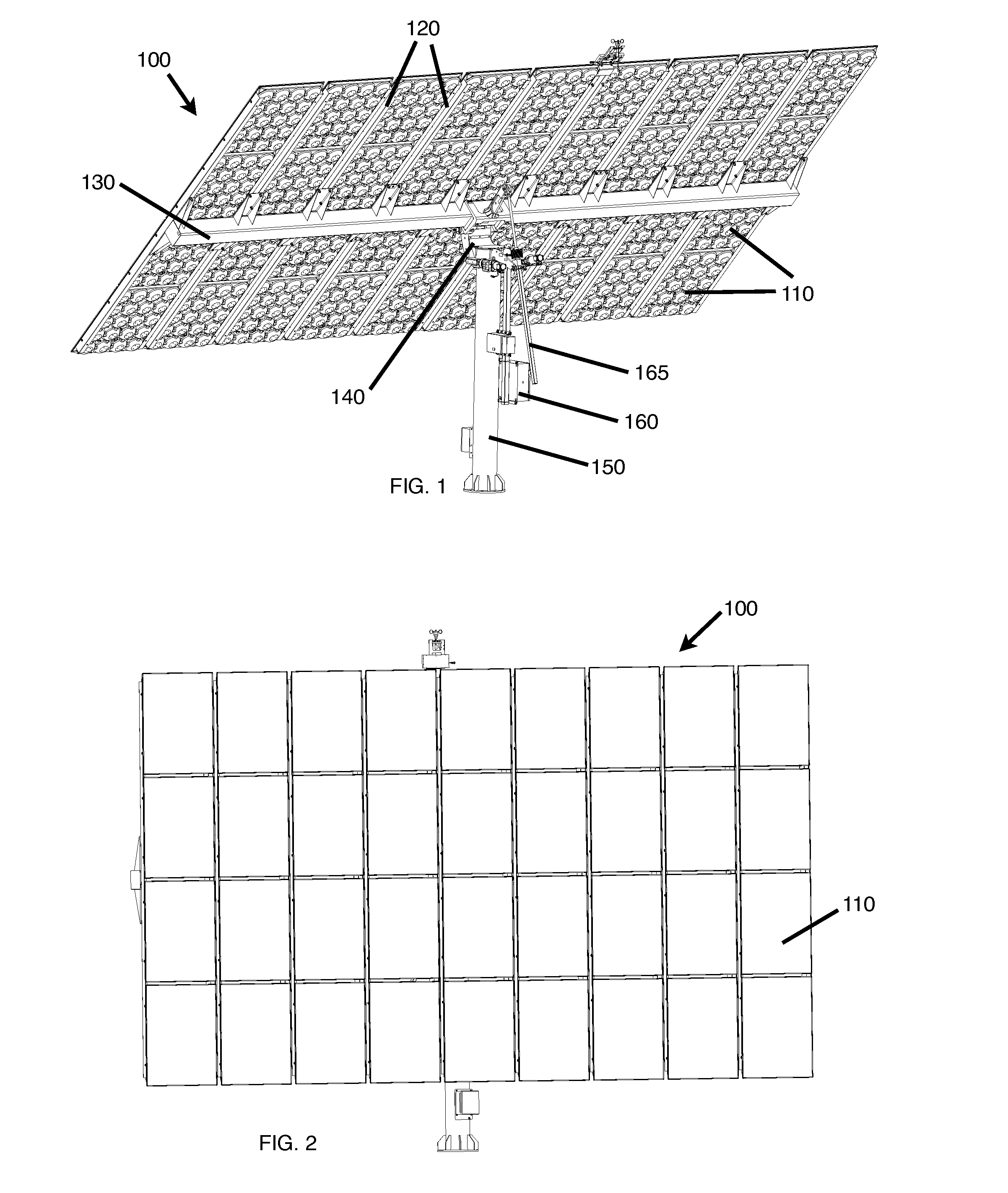
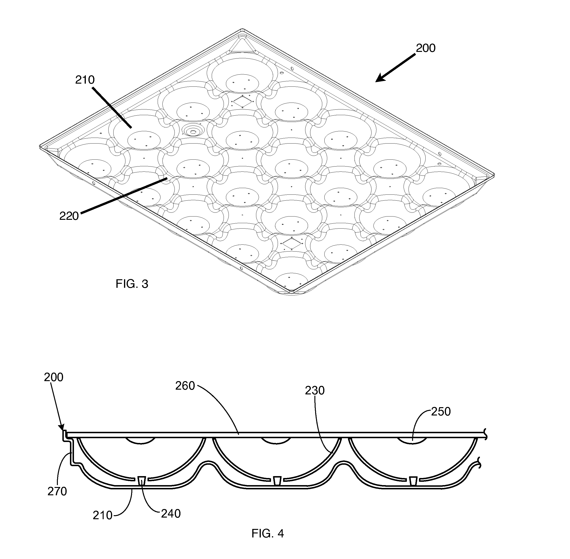
[0014]A solar panel assembly is disclosed in which rails are combined with one or more structurally rigid backpans to form a multi-panel assembly that requires minimal support when mounted to a tracking system. In typical solar energy installations, solar panels are designed as a piece of equipment to be mounted and aligned only, with the tracking system and auxiliary components being relied upon for the structural integrity of the overall installed solar assembly. By designing a solar panel assembly as a structural component as in the present invention, the amount of supporting framework that is required is simplified compared to conventional tracking systems. Consequently, costs associated with material and with installation of a solar energy system are reduced. Pedestal-type mounts, which conventionally require substantial support of the cantilever-type mounting of solar panels onto a central pedestal, can particularly benefit greatly from such a design. In addition, advantages r...


PUM

PropertyMeasurementUnit
thicknessaaaaaaaaaa
widthaaaaaaaaaa
thicknessaaaaaaaaaa

Abstract

A solar concentrator assembly includes a pair of rails coupled together only by one or more backpans which are mounted between the pair of rails. The rails are configured to resist a portion of a cantilever deflection along the length of the rails. The backpans seat solar concentrator arrays and are configured to provide torsional rigidity and deflection resistance in at least one direction orthogonal to the cantilever deflection.

Description

RELATED APPLICATIONS[0001]This application claims priority to U.S. Provisional Patent Application No. 61 / 528,743 filed Aug. 29, 2011, entitled “Solar Assembly Structure,” and which is hereby incorporated by reference for all purposes.BACKGROUND OF THE INVENTION[0002]In the production of solar energy, arrays of solar collectors are typically mounted onto a tracking system. The tracking system changes the angular orientation of the solar collectors, such as solar panels or arrays, so that they are directed toward the sun in order to maximize solar collection. Numerous solar arrays are mounted on one tracker, and consequently the tracker conventionally requires a substantial structural framework involving beams, trusses, and the like to support the weight of the arrays. For pedestal-mounted systems in particular, an expansive solar module atop a single pole serves a large cantilever, requiring heavy frames and materials to resist the high wind loads resulting from this type of design.[...

Claims


Application Information

Patent Timeline
Patent Type & Authority Applications(United States)
IPC IPC(8): H01L31/042
CPCH01L31/0424Y02E10/52F24J2/5232F24J2/5237Y10T29/49826Y02E10/47H02S20/00H01L31/0547F24J2/542H02S20/32F24S25/11F24S30/452F24S25/12
Inventor MAGALHAES, PEDROSCHRADIN, AARONCHOI, DONG HOGREEN, EVAN
Owner SOLFOCUS
Why Eureka
Try Eureka